Modification - SD49225T-HN Increase Upward Tilt Range

guykuo

Getting comfortable
Joined
Jul 7, 2018
Messages
581
Reaction score
1,455
Location
Sammamish, WA
Advanced Modification Disclaimer - I successfully performed this modification, but this should only be undertaken with the understanding that you may damage your camera permanently. Only those who are mechanically inclined and familiar with plastic welding/3D printing with PLA should attempt this mod. You are solely responsible for any damages caused by doing this modification.

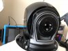
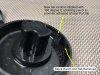
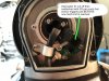
This modification provides shifts the tilt range of the camera upward. Post mod, it can look about about 37 degrees up - direct at edge of upper casing. The trade off is it, but can only look down to about 70 degrees. I never need my PTZ's to look straight down, but often wished for a few more degrees up. This mod accomplishes that, but it is not an easy one.

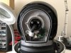
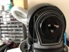
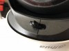
First you must remove both side covers. The four screws on each side are obvious, but there are also screws hidden under the rubber plugs.
01 side screws.jpg 02 screws under rubber plugs.jpg
 
Last edited:

guykuo

Getting comfortable
Joined
Jul 7, 2018
Messages
581
Reaction score
1,455
Location
Sammamish, WA
03 drive side.jpg
One side of the camera has the drive belt and gear. The gear has a tab on its inside. That tab acts as the hard limit for tilt motion.
 
Last edited:

guykuo

Getting comfortable
Joined
Jul 7, 2018
Messages
581
Reaction score
1,455
Location
Sammamish, WA
The other side of the camera has the upward tilt limit sensor. The camera normally only tilts up only until the limit sensor is triggered.
04 limit sensor side.jpg
 

guykuo

Getting comfortable
Joined
Jul 7, 2018
Messages
581
Reaction score
1,455
Location
Sammamish, WA
To shift the tilt range upward, both the limit sensor and the hard limit tab must be modified. This involves physical modification of plastic pieces. Going back is possible but you'd have to undo your changes. By modification, I mean moving limits by cutting existing plastic features and recreating those bits with a 3D pen and PLA.


Remove the drive gear. Three screws hold it in place. Slide is straight out. There will be some slight resistance to pulling out the gear due to the drive belt. DO NOT ROTATE the mounting hub relative to the camera globe.

I've now done this on 4 of my Dahua PTZ's. (Also 2 of my Sunbas, but that's a different method). On 1 of 4 Dahua there was thread lock on 2 gear retention screws. Not all cameras, not all screws, but made removing the screws challenging. Fortunately, the other three were not thread locked.
05 remove drive gear.jpg
 
Last edited:

guykuo

Getting comfortable
Joined
Jul 7, 2018
Messages
581
Reaction score
1,455
Location
Sammamish, WA
The hard limit tab is on the inside of the drive gear. It impinges against the metal extrusions to hard limit the camera tilt. We must move that hard limit by removing the existing tab and creating a new one in the desired location.
06 hard limit tab.jpg
 

guykuo

Getting comfortable
Joined
Jul 7, 2018
Messages
581
Reaction score
1,455
Location
Sammamish, WA
Here you can see the new location has been stippled with the soldering iron so the new PLA will adhere solidly.
07 new tab location.jpg
 

guykuo

Getting comfortable
Joined
Jul 7, 2018
Messages
581
Reaction score
1,455
Location
Sammamish, WA
As an Amazon Associate IPCamTalk earns from qualifying purchases.

guykuo

Getting comfortable
Joined
Jul 7, 2018
Messages
581
Reaction score
1,455
Location
Sammamish, WA
The new tab has been fabricated out of PLA. You might want to practice 3D printing and shaping before actually working on the gear.

Put your modified gear back onto the camera and drive belt before you proceed to the other side of the camera. Putting the gear back on is tricky because you must also ensure the drive belt is engaged with the motor gear (deep in the camera) as well as the gear you are putting back on. I first checked that the belt was engaged with the small motor gear. Then tilted the camera sphere anticlockwise before slipping the gear partially in. Draping the belt over part of the gear and then rotating the sphere clockwise while gradually pushing in the gear got things reconnected. You may have to open the camera further to set the belt if my rotation trick doesn't work for you. Getting the belt back on is probably the trickiest part of this mod. You should feel slight resistance of the motor as you tilt the sphere if you have the belt properly on the small motor gear.
09 new hard limit tab.jpg
 

guykuo

Getting comfortable
Joined
Jul 7, 2018
Messages
581
Reaction score
1,455
Location
Sammamish, WA
Next we modify the tilt sensor. The interrupter fin needs to be repositioned such that it triggers just before the new hard limit is reached. I cut off the fin and reattached it in the new position.


To determine the new fin position, tilt the camera sphere to its new max up hard stop. The fin should be reattached centered in the sensor. A small piece of paper folded to the right thickness on each side of the fin helps center it in the sensor groove. The fin should aligned so it will interrupt just BEFORE camera hits max upward tilt.
10 limit sensor.jpg
 

guykuo

Getting comfortable
Joined
Jul 7, 2018
Messages
581
Reaction score
1,455
Location
Sammamish, WA
11 limit fin repositioned.jpg

Test your camera by powering it up. The motion calibrations should occur without any loud noises or snags. If you note anything hanging up or reaching limits, re-evaluation your sensor and hard limit mods. If vertical tilt doesn't move, your belt isn't properly engaged on both gears.
 

guykuo

Getting comfortable
Joined
Jul 7, 2018
Messages
581
Reaction score
1,455
Location
Sammamish, WA
Stock max tilt up
stock max tilt up.jpg

With modification, the camera can actually tilt up even further than the below image. It can point far up enough to bring the dome cover edge nearly to image center. Now I can find those birds at the top of trees.

Downward tilt still lets me check the ground to within 2 feet of my mounting pole base.
modified tilt up.jpg
 

guykuo

Getting comfortable
Joined
Jul 7, 2018
Messages
581
Reaction score
1,455
Location
Sammamish, WA
Over two year follow-up. My upward tilt enhanced Dahua PTZ's are still working fine. This despite over two years of full exposure to cold and sun - with their entire bodies painted flat black.
 

wittaj

IPCT Contributor
Joined
Apr 28, 2019
Messages
24,952
Reaction score
48,657
Location
USA
Thanks - I always love your detailed explanations on how you modified something. I was wishing my PTZ went up higher - now I know of a mod to do so!
 

SyconsciousAu

Getting comfortable
Joined
Sep 13, 2015
Messages
872
Reaction score
825
Over two year follow-up. My upward tilt enhanced Dahua PTZ's are still working fine. This despite over two years of full exposure to cold and sun - with their entire bodies painted flat black.
You are a braver man than I, but I can see the need for a modification like this one, especially if you live at the bottom of a hill and want to see up it.
 
Top