
Blue Iris and IOT ( Internet of things)
Hi All.
After a few months of work I have finally put together a www.iiot.co.za website containing all promised below.
Having also sent Ken an email about enabling Blue Iris for MQTT to aid development in the IOT and home automation space I have in the interim kicked off a Email 2 MQTT gateway product.
The product will allow alerts sent by general email clients and Blue Iris software to be published to MQTT topics for further execution by IOT devices and applications.
There are also many other solutions for IOT and home automation on the website.
Please see this solution and more here http://www.iiot.co.za
eBook: How to setup Email to MQTT gateway with Arduino UNO R3
For all of you who register from IPCAMTalk please apply a discount code of IPCAM to your carts on checkout for a 20% discount on all products (if purchasing anything.)
This coupon is valid for March 2016.
Thank you all, chat soon.
-------------------
Hi Everyone.
Firstly a big thank you to IP CamTalk for having such a rich and open platform, ... thanks you guys are amazing!
OK, in my last "FreeBee" post far below I hinted that I was working on a new wireless solution......................
Further below you will find my "FreeBee" post on integrating Arduino and Blue Iris, If you want to plug a Arduino in with a Serial cable, well that's good and fine but for some of you, you will rather want to integrate Blue Iris with limitless cross-functional IOT (Internet of things).
So.. I have started a new post called Blue IRIS and the IOT ( Internet of things), again donations are welcome to keep up the R&D and you are welcome to PM me on iot1@kldtechnologies.co.za with subject BI-IOT if you are interested in purchasing detailed document ($10 for +- 60 pages) practical real-world working code, professionally laid out PCB build, how to's for setting up Arduino UNO, Ethernet Shield, OpenHAB, MQTT and the wireless IOT chips the ESP8266-01 and ESP8266-12 (Firmware, locked loops, coding etc.)
For those of you who purchase the documentation will be able to download all code and reference material.
O.K, so let's get started.
We are NOT going to connect Blue Iris alerts via a serial cable to an Arduino anymore but we will still be using the following components.
for ..BLUE IRIS BITS:
Arduino UNO
W5100 series Ethernet Shield
for..IOT BITS:
OpenHAB
MQTT Mosquitto
Ubuntu Server
ESP8266-12
In this post I will cover the general concept of what we are doing and stop at the point after the Arduino with Ethernet Shield setups.
CONCEPT:
Blue Iris Camera Alerts are setup to send and alert email to a POP mail server with a specific subject (this is not your Arduino), you can setup these in you BI software on the fly.
The Arduino is powered on and connected to the network constantly checking for emails.
The Arduino has an attached Ethernet Shield Board and the Arduino is setup to retrieve the email and publish a message to a MQTT broker(the MQTT could be your own or something like thingspeak etc.).
The IOT bit....
The MQTT broker service in turn updates OpenHAB and controls the GPIO pins on the ESP8266-12.(7 switchable GPIO's per ESP-12, unlimited ESP-12's)
Basically if you can switch a GPIO/LED either ON/OFF or PULSE (ON then OFF) then you can integrate it into anything you like.
So here is a demonstration of this in action using OpenHAB, however as Blue Iris emails are converted to MQTT messages the alerts from BLue IRIS will have the same effect as me switching on and off the LED's using OpenHAB as I did in the video.
Please note I have thoroughly tested the working EMAIL -> MQTT conversion.
Additionally any MQTT client or application be it Linux, Windows, or Mobile devices IOS, Android of WindowsMobile that has an app that can publish to a MQTT broker service will also be able to control your devices.... no absolute dependency on Openhab!!!
You can also run a small MQTT broker service on your Windows PC.
A lot of thought time and coding went into this project and I will gladly share all I have for a donation, I have displayed the technical abilities in my first "freebee" post so here is the link below and if you would like to get all my designs, builds and working code for all components please donate and PM me on iot1@kldtechnologies.co.za.

Additionally, I would ask that Blue Iris consider adding MQTT subscription capability to the software set which will further enhance its capability.
Ken, any thoughts or insights from your side?
Bye for now.
----------------------------------------------------------------- Older "FreeBee" Post --------------------------------------------------------------------------
Hello.
Before we begin it is important to note that all pictures, links, attachments and videos may not be visible in this post if you are not logged in.
Most posts are aimed at asking question but this post is aimed at contributing some successful R&D and helping users to integrate Arduino with Blue Iris outputs.
The post also describes the connection and integration of an Arduino UNO R3 to Blue Iris ver 4.0.9.xx which will enable the DIO output control found in the latest Blue Iris mobile application to control or operate mechanical output relays.
Additionally it will cover how to set per camera digital output bit's also enabling the control of mechanical relays from alert events on cameras, whether triggered through motion or manually on the camera video/dialog screen.
The post includes the working and tested Arduino sketches as well as project simulation sketches that can be used in virtual bread board for Arduino (VBB4 Arduino), available as attachments further below.
The code was also tested on a fail safe basis, in other words if you have a power failure or you connect your Arduino you do not want things switching on and off.
This post will be followed by more posts covering the DIO input aspects to activate cameras using PIR/Sensor/etc. from the Arduino itself and culminate in further posts outlining the IoT development where wireless ESP and Xbee distributed IO will be possible.
The use of Arduino, a simple conversion circuit and a standard off the shelf opto isolated relay board works out at around 1/3 the price of a Open Sealevel SeaDAC device and can provide more flexibility and function, I am sure that the SeaDAC devices add a lot of convenience and simplicity but were a little pricey for my pocket.
A lot of work went into developing the material covered in this post possibly saving you money in having to buy more shrink wrapped solutions and any donations would be welcome to assist me in further R&D.
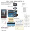
The Architectural and design Diagram.
Arduino & Blue Iris Integration
Please note the "GCE Electronics" Protocol under "Serial Port" for "Digital I/O" was used within "Blue Iris Options" for the development below.

The Arduino UNO R3 working sketch: attachment "BlueIris_v2.0.txt" , just rename the extension to .ino

The Arduino UNO R3 working project: attachment "BlueIris_v2.0.zip.txt", just remove the .txt and import it into Virtual Bread Board for Arduino, VBB4Adruino Simulator can be found here:

Version Notes and General Comments:
On Blue Iris versions 4.0.3.1 the Alert(output) to serial , set in bits 1,2,3,4,5,6,7,8 produce a ASCII output of S01,S11,S21,S31,S41,S51,S61,S71 for ON and for OFF the corresponding, S00, S10, S20,S30,S40,S50, S60,S70
so the serial read if loop should read in the first three bytes, then process. "if (Serial.available() > 2) {}"
In Blue Iris versions 4.0.9.x, the outputs for DIO Trigger Output and Alerts trigger output changed, the full map is in my posted code.
essentially Alert bit's 16, 32, 64, 128 produce an corresponding ASCII output to serial of S41,S51,S61,S71 for ON and correspondingly S40,S50,S60, S70 for OFF.
The DIO output triggers in the app generate S01,S11,S21,S31 for ON and correspondingly a S00,S10,S20, S30 for OFF.
I have written my serial.read Arduino code to look at three bytes " > 2", but if you want to do some other funky stuff I suggest you run a serial port monitor, observe the serial outputs from Blue Iris and then write your code to suit.
Any decent serial port monitor will do, in my case I found Eltima Serial port monitor to be quite useful, you can find them here:
I also found the serial port drivers bundled in the Arduino IDE (Integrated Development Environment) to work fine for the serial port monitor and the Blue Iris application, you can download the Arduino IDE here:
I have also made two small demonstration videos available on you tube if you would like to see it all in action.
Video 01: TheSetup - This small video shows the setup of the 8 relayboard connected via intermediate PCB circuit to Arduino Uno R3
Video 02: TestingAlertThenDIOOutput - This small video demonstrates the Arduino code in action with Blue Iris, here we first setup the alerts with 16,32,64,128 bits and trigger an alert manually for each setting thus operating relays 5-6 each at a time demonstrating each relay in succession switching with each setting, then the video demonstrates the switching of relays 1-4 using the Blue Iris IOS app on a Apple iPad air, and then the video finales with the alert being triggered from the camera view on the iPad.
The activating and deactivating mechanical relays are visible by the red LED's on the 8 Relay module in the top right of the video.
I do apologise for the quality of the video but it is the best I can do with the video kit I have at my disposal.
If you have found this useful and would like to donate to further my R&D posts please do so on the donate button below (Any amount would be most appreciated)
18-07-2015
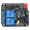
A 2 Channel Relay Board Shield can be plugged directly into the Arduino UNO, serial.write data S61, S71 for ON and S60,S70 for OFF from my downloadable code work right out of the box with the two relays, see picture below.

Not advertising for the company, but if you want the spec, you can find it here.http://www.dx.com/p/2-channel-relay-shield-module-for-arduino-w-xbee-btbee-interface-141544#.VaoASGYaLIU
No need for external power supply, just the serial cable connected to the Arduino UNO is sufficient to power the relays.
Hi All.
After a few months of work I have finally put together a www.iiot.co.za website containing all promised below.
Having also sent Ken an email about enabling Blue Iris for MQTT to aid development in the IOT and home automation space I have in the interim kicked off a Email 2 MQTT gateway product.
The product will allow alerts sent by general email clients and Blue Iris software to be published to MQTT topics for further execution by IOT devices and applications.
There are also many other solutions for IOT and home automation on the website.
Please see this solution and more here http://www.iiot.co.za
eBook: How to setup Email to MQTT gateway with Arduino UNO R3
For all of you who register from IPCAMTalk please apply a discount code of IPCAM to your carts on checkout for a 20% discount on all products (if purchasing anything.)
This coupon is valid for March 2016.
Thank you all, chat soon.
-------------------
Hi Everyone.
Firstly a big thank you to IP CamTalk for having such a rich and open platform, ... thanks you guys are amazing!
OK, in my last "FreeBee" post far below I hinted that I was working on a new wireless solution......................
Further below you will find my "FreeBee" post on integrating Arduino and Blue Iris, If you want to plug a Arduino in with a Serial cable, well that's good and fine but for some of you, you will rather want to integrate Blue Iris with limitless cross-functional IOT (Internet of things).
So.. I have started a new post called Blue IRIS and the IOT ( Internet of things), again donations are welcome to keep up the R&D and you are welcome to PM me on iot1@kldtechnologies.co.za with subject BI-IOT if you are interested in purchasing detailed document ($10 for +- 60 pages) practical real-world working code, professionally laid out PCB build, how to's for setting up Arduino UNO, Ethernet Shield, OpenHAB, MQTT and the wireless IOT chips the ESP8266-01 and ESP8266-12 (Firmware, locked loops, coding etc.)
For those of you who purchase the documentation will be able to download all code and reference material.
O.K, so let's get started.
We are NOT going to connect Blue Iris alerts via a serial cable to an Arduino anymore but we will still be using the following components.
for ..BLUE IRIS BITS:
Arduino UNO
W5100 series Ethernet Shield
for..IOT BITS:
OpenHAB
MQTT Mosquitto
Ubuntu Server
ESP8266-12
In this post I will cover the general concept of what we are doing and stop at the point after the Arduino with Ethernet Shield setups.
CONCEPT:
Blue Iris Camera Alerts are setup to send and alert email to a POP mail server with a specific subject (this is not your Arduino), you can setup these in you BI software on the fly.
The Arduino is powered on and connected to the network constantly checking for emails.
The Arduino has an attached Ethernet Shield Board and the Arduino is setup to retrieve the email and publish a message to a MQTT broker(the MQTT could be your own or something like thingspeak etc.).
The IOT bit....
The MQTT broker service in turn updates OpenHAB and controls the GPIO pins on the ESP8266-12.(7 switchable GPIO's per ESP-12, unlimited ESP-12's)
Basically if you can switch a GPIO/LED either ON/OFF or PULSE (ON then OFF) then you can integrate it into anything you like.
So here is a demonstration of this in action using OpenHAB, however as Blue Iris emails are converted to MQTT messages the alerts from BLue IRIS will have the same effect as me switching on and off the LED's using OpenHAB as I did in the video.
Please note I have thoroughly tested the working EMAIL -> MQTT conversion.
Additionally any MQTT client or application be it Linux, Windows, or Mobile devices IOS, Android of WindowsMobile that has an app that can publish to a MQTT broker service will also be able to control your devices.... no absolute dependency on Openhab!!!
You can also run a small MQTT broker service on your Windows PC.
A lot of thought time and coding went into this project and I will gladly share all I have for a donation, I have displayed the technical abilities in my first "freebee" post so here is the link below and if you would like to get all my designs, builds and working code for all components please donate and PM me on iot1@kldtechnologies.co.za.
Additionally, I would ask that Blue Iris consider adding MQTT subscription capability to the software set which will further enhance its capability.
Ken, any thoughts or insights from your side?
Bye for now.
----------------------------------------------------------------- Older "FreeBee" Post --------------------------------------------------------------------------
Hello.
Before we begin it is important to note that all pictures, links, attachments and videos may not be visible in this post if you are not logged in.
Most posts are aimed at asking question but this post is aimed at contributing some successful R&D and helping users to integrate Arduino with Blue Iris outputs.
The post also describes the connection and integration of an Arduino UNO R3 to Blue Iris ver 4.0.9.xx which will enable the DIO output control found in the latest Blue Iris mobile application to control or operate mechanical output relays.
Additionally it will cover how to set per camera digital output bit's also enabling the control of mechanical relays from alert events on cameras, whether triggered through motion or manually on the camera video/dialog screen.
The post includes the working and tested Arduino sketches as well as project simulation sketches that can be used in virtual bread board for Arduino (VBB4 Arduino), available as attachments further below.
The code was also tested on a fail safe basis, in other words if you have a power failure or you connect your Arduino you do not want things switching on and off.
This post will be followed by more posts covering the DIO input aspects to activate cameras using PIR/Sensor/etc. from the Arduino itself and culminate in further posts outlining the IoT development where wireless ESP and Xbee distributed IO will be possible.
The use of Arduino, a simple conversion circuit and a standard off the shelf opto isolated relay board works out at around 1/3 the price of a Open Sealevel SeaDAC device and can provide more flexibility and function, I am sure that the SeaDAC devices add a lot of convenience and simplicity but were a little pricey for my pocket.
A lot of work went into developing the material covered in this post possibly saving you money in having to buy more shrink wrapped solutions and any donations would be welcome to assist me in further R&D.
The Architectural and design Diagram.
Arduino & Blue Iris Integration
Please note the "GCE Electronics" Protocol under "Serial Port" for "Digital I/O" was used within "Blue Iris Options" for the development below.
The Arduino UNO R3 working sketch: attachment "BlueIris_v2.0.txt" , just rename the extension to .ino
The Arduino UNO R3 working project: attachment "BlueIris_v2.0.zip.txt", just remove the .txt and import it into Virtual Bread Board for Arduino, VBB4Adruino Simulator can be found here:
Version Notes and General Comments:
On Blue Iris versions 4.0.3.1 the Alert(output) to serial , set in bits 1,2,3,4,5,6,7,8 produce a ASCII output of S01,S11,S21,S31,S41,S51,S61,S71 for ON and for OFF the corresponding, S00, S10, S20,S30,S40,S50, S60,S70
so the serial read if loop should read in the first three bytes, then process. "if (Serial.available() > 2) {}"
In Blue Iris versions 4.0.9.x, the outputs for DIO Trigger Output and Alerts trigger output changed, the full map is in my posted code.
essentially Alert bit's 16, 32, 64, 128 produce an corresponding ASCII output to serial of S41,S51,S61,S71 for ON and correspondingly S40,S50,S60, S70 for OFF.
The DIO output triggers in the app generate S01,S11,S21,S31 for ON and correspondingly a S00,S10,S20, S30 for OFF.
I have written my serial.read Arduino code to look at three bytes " > 2", but if you want to do some other funky stuff I suggest you run a serial port monitor, observe the serial outputs from Blue Iris and then write your code to suit.
Any decent serial port monitor will do, in my case I found Eltima Serial port monitor to be quite useful, you can find them here:
I also found the serial port drivers bundled in the Arduino IDE (Integrated Development Environment) to work fine for the serial port monitor and the Blue Iris application, you can download the Arduino IDE here:
I have also made two small demonstration videos available on you tube if you would like to see it all in action.
Video 01: TheSetup - This small video shows the setup of the 8 relayboard connected via intermediate PCB circuit to Arduino Uno R3
Video 02: TestingAlertThenDIOOutput - This small video demonstrates the Arduino code in action with Blue Iris, here we first setup the alerts with 16,32,64,128 bits and trigger an alert manually for each setting thus operating relays 5-6 each at a time demonstrating each relay in succession switching with each setting, then the video demonstrates the switching of relays 1-4 using the Blue Iris IOS app on a Apple iPad air, and then the video finales with the alert being triggered from the camera view on the iPad.
The activating and deactivating mechanical relays are visible by the red LED's on the 8 Relay module in the top right of the video.
I do apologise for the quality of the video but it is the best I can do with the video kit I have at my disposal.
If you have found this useful and would like to donate to further my R&D posts please do so on the donate button below (Any amount would be most appreciated)
A 2 Channel Relay Board Shield can be plugged directly into the Arduino UNO, serial.write data S61, S71 for ON and S60,S70 for OFF from my downloadable code work right out of the box with the two relays, see picture below.
Not advertising for the company, but if you want the spec, you can find it here.http://www.dx.com/p/2-channel-relay-shield-module-for-arduino-w-xbee-btbee-interface-141544#.VaoASGYaLIU
No need for external power supply, just the serial cable connected to the Arduino UNO is sufficient to power the relays.
Attachments
-
 260.2 KB Views: 978
 -
7.3 KB Views: 1,245
-
4.9 KB Views: 1,156
-
 1.4 KB Views: 1,285
 -
 69.7 KB Views: 827
Last edited by a moderator: