I’ve seen some examples of Arduino code for trigger Blue Iris on the forum, but don’t think I’ve seen anyone that uses both write and read from/to Blue Iris. Anyhow I think Blue Iris is great software and wanted to share my Arduino code and maybe someone can use the hole or part of it. I’m a beginner at coding so it isn’t pretty but I hope it’s rather easy to follow. See attached file for the code.
Set GCE electronics protocol in the Digital I/O tab in Blue Iris.
I've used this code on an Arduino Uno.
Basically this is how the code works if you don’t do any changes in it.
Trigger Output from Blue Iris Alerts. (Rewriting the code and you can get 4 additional outputs)
In Blue Iris -> “Set digital output bits (1+2+4+8)”
If Blue Iris is set to 1 => Arduino I/O pin 10 will be high for the triggered time. (Set as Output pin in Arduino)
If Blue Iris is set to 2 => Arduino I/O pin 11 will be high for the triggered time. (Set as Output pin in Arduino)
If Blue Iris is set to 4 => Arduino I/O pin 12 will be high for the triggered time. (Set as Output pin in Arduino)
If Blue Iris is set to 8 => Arduino I/O pin 13 will be high for the triggered time. (Set as Output pin in Arduino)
Trigger Input to Blue Iris camera Motion/trigger (Mostly what I'm using this program to, PIR sensors that triggers the cameras)
In Blue Iris set “Trigger with DIO input bits” to 1,2,4,8,16,32,64 or 128
If Arduino I/O pin 2 (Set as Input pin in Arduino) will be high then Blue Iris will trigger on => 1
If Arduino I/O pin 3 (Set as Input pin in Arduino) will be high then Blue Iris will trigger on => 2
If Arduino I/O pin 4 (Set as Input pin in Arduino) will be high then Blue Iris will trigger on => 4
If Arduino I/O pin 5 (Set as Input pin in Arduino) will be high then Blue Iris will trigger on => 8
If Arduino I/O pin 6 (Set as Input pin in Arduino) will be high then Blue Iris will trigger on => 16
If Arduino I/O pin 7 (Set as Input pin in Arduino) will be high then Blue Iris will trigger on => 32
If Arduino I/O pin 8 (Set as Input pin in Arduino) will be high then Blue Iris will trigger on => 64
If Arduino I/O pin 9 (Set as Input pin in Arduino) will be high then Blue Iris will trigger on => 128
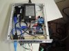
How to connect it electrically you find on several forums, I use relays to separate the signals between the Arduino and my PIR sensors.
Set GCE electronics protocol in the Digital I/O tab in Blue Iris.
I've used this code on an Arduino Uno.
Basically this is how the code works if you don’t do any changes in it.
Trigger Output from Blue Iris Alerts. (Rewriting the code and you can get 4 additional outputs)
In Blue Iris -> “Set digital output bits (1+2+4+8)”
If Blue Iris is set to 1 => Arduino I/O pin 10 will be high for the triggered time. (Set as Output pin in Arduino)
If Blue Iris is set to 2 => Arduino I/O pin 11 will be high for the triggered time. (Set as Output pin in Arduino)
If Blue Iris is set to 4 => Arduino I/O pin 12 will be high for the triggered time. (Set as Output pin in Arduino)
If Blue Iris is set to 8 => Arduino I/O pin 13 will be high for the triggered time. (Set as Output pin in Arduino)
Trigger Input to Blue Iris camera Motion/trigger (Mostly what I'm using this program to, PIR sensors that triggers the cameras)
In Blue Iris set “Trigger with DIO input bits” to 1,2,4,8,16,32,64 or 128
If Arduino I/O pin 2 (Set as Input pin in Arduino) will be high then Blue Iris will trigger on => 1
If Arduino I/O pin 3 (Set as Input pin in Arduino) will be high then Blue Iris will trigger on => 2
If Arduino I/O pin 4 (Set as Input pin in Arduino) will be high then Blue Iris will trigger on => 4
If Arduino I/O pin 5 (Set as Input pin in Arduino) will be high then Blue Iris will trigger on => 8
If Arduino I/O pin 6 (Set as Input pin in Arduino) will be high then Blue Iris will trigger on => 16
If Arduino I/O pin 7 (Set as Input pin in Arduino) will be high then Blue Iris will trigger on => 32
If Arduino I/O pin 8 (Set as Input pin in Arduino) will be high then Blue Iris will trigger on => 64
If Arduino I/O pin 9 (Set as Input pin in Arduino) will be high then Blue Iris will trigger on => 128
How to connect it electrically you find on several forums, I use relays to separate the signals between the Arduino and my PIR sensors.
Attachments
-
1.8 KB Views: 242