Breakrellom
n3wb
So,
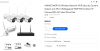
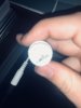
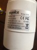
I’m new to all of this, I am pretty tech savvy for the most part but I am stumped. I have a 8ch 1080p SANNCE NVR wireless system, came with 4 cameras paired to NVR, i was considering changing interface so I was changing the camera ip’s to my network’s gateway, well silly me conflicted the first camera, so it umpired. No biggie, I just plug the Ethernet into camera and square it away, when I attempted to do so, I realize the RJ45 network connector was chewed up and missing one, had to have came with that, and when I attempted to call I was talking to a brick wall, then I went to email support for assistance but the email was returned, needless to say I gave up on that, so I watched a video where the guy cut the connector off, put a male end on the wires, attached to female coupler and had Ethernet connect to router. But I can not for the life of me find a Pinout or any diagrams, I had to rush out of the door and my dogs ruined any chance of knowing what wires were what. I do however, have a couple pictures.
every post I see has color wires I don’t. I only have to connect to router to resolve IP issue then it’s back to wireless. Anybody have any beginner friendly advice? And trust me, I already ordered other cameras so I just hate to see the thing just sit in a bin, and It’s more for the learning experience
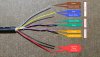
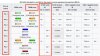
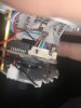
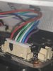
the wires are:
Purple
Blue
White/Blue
Green
White/Green
Black
Red
in that order, no orange, no brown, no grey. And I don’t know if I just have other end as same order or how that works
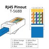
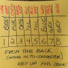
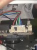
**UPDATE** I fixed it, was tired of searching for the right answer and used logic, if all I was seeking was Ethernet power, then worry about the RJ45 wires so I just used the 4 wires and let the rest dangle, Blue/White - Pin 1, Blue - Pin 2, Green/White - Pin 3, Green - Pin 6, worked like a charm.
I’m new to all of this, I am pretty tech savvy for the most part but I am stumped. I have a 8ch 1080p SANNCE NVR wireless system, came with 4 cameras paired to NVR, i was considering changing interface so I was changing the camera ip’s to my network’s gateway, well silly me conflicted the first camera, so it umpired. No biggie, I just plug the Ethernet into camera and square it away, when I attempted to do so, I realize the RJ45 network connector was chewed up and missing one, had to have came with that, and when I attempted to call I was talking to a brick wall, then I went to email support for assistance but the email was returned, needless to say I gave up on that, so I watched a video where the guy cut the connector off, put a male end on the wires, attached to female coupler and had Ethernet connect to router. But I can not for the life of me find a Pinout or any diagrams, I had to rush out of the door and my dogs ruined any chance of knowing what wires were what. I do however, have a couple pictures.
every post I see has color wires I don’t. I only have to connect to router to resolve IP issue then it’s back to wireless. Anybody have any beginner friendly advice? And trust me, I already ordered other cameras so I just hate to see the thing just sit in a bin, and It’s more for the learning experience
the wires are:
Purple
Blue
White/Blue
Green
White/Green
Black
Red
in that order, no orange, no brown, no grey. And I don’t know if I just have other end as same order or how that works
**UPDATE** I fixed it, was tired of searching for the right answer and used logic, if all I was seeking was Ethernet power, then worry about the RJ45 wires so I just used the 4 wires and let the rest dangle, Blue/White - Pin 1, Blue - Pin 2, Green/White - Pin 3, Green - Pin 6, worked like a charm.
Attachments
-
 1.5 MB Views: 62
 -
 1.9 MB Views: 66
 -
 998.3 KB Views: 64
 -
 1 MB Views: 61
 -
 955.4 KB Views: 59
 -
 1 MB Views: 54
Last edited: