Dahua alarm input / output

steve hollis

Young grasshopper
Joined
May 13, 2018
Messages
55
Reaction score
8
Hello everyone,
Got myself a Dahua DH-IPC-HDBW81230E dome camera from Andy @ Empiretech (Great service I must mention!) but not wishing to fry the circuits, am having this terrible disagreement with myself on how to wire the alarm input / output.
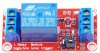
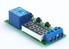
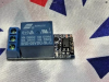
I have set up a tripwire and want to fire a 230v strobe when triggered. I have eBayed myself a 12v/230v relay and the 230v side is all wired. That leaves the relay 12v which just has + & -.
My first thought is to directly connect the positive to the relay and run the negative into the input and out of the output, hoping this will trigger the relay on an event?
It might be something camera model specific however, because Ive been reading that you shouldn't use 12v, some posts mention using 3.3v.
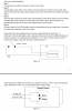
The quick start guide of the camera doesn't mention 3.3v but does mention a 12/24v port. When opening the dome, this port already has 2 wires connected so didn't think adding 12v power to here was a good idea either.
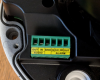
I then think if the input/output does only work with small voltages, do I get a 3.3v/12v relay, then connect this to my 12v/230v relay - have a feeling this isn't the best way either. I will try and include the I/O image and a second image is from the quick start guide with the instructions. Maybe I'm just not reading them properly?
I'd be most grateful in some help on this.
input output.png


quick start.png
 

bababouy

Known around here
Joined
Mar 29, 2015
Messages
1,053
Reaction score
1,630
Location
almost to the bottom
This is just a dry contact, whether its in or out. Don't send power through it. Use the output to trigger a relay that has power running from one side to the other. Same with the input.
 

tangent

IPCT Contributor
Joined
May 12, 2016
Messages
4,422
Reaction score
3,656
This is just a dry contact, whether its in or out. Don't send power through it. Use the output to trigger a relay that has power running from one side to the other. Same with the input.
in other words you need a 3.3/3v opto-isolated relay.

You still need a relay, but I'd use a 12v strobe. Safer and plenty bright.
 

steve hollis

Young grasshopper
Joined
May 13, 2018
Messages
55
Reaction score
8
Ok, I’m going to look out for a suitable3.3/3v opto-isolated relay. Just happen to have a job lot of mains strobe photographic units so makes sense to use what I’ve already got.
Just 2 more questions. What’s a opto-isolated relay ?
And could one of you draw me a little pencil diagram showing how my I/O connectors - connect up, please.
IN / ALARM GND / OUT
as my head is swimming a bit
Regards Steve
 

tangent

IPCT Contributor
Joined
May 12, 2016
Messages
4,422
Reaction score
3,656
Opto-isolator - Wikipedia

I was referring to cheap boards you can find that combine a opto-isolator and relay with a low voltage control signal. You may also require a pull up resistor Pull-up resistor - Wikipedia

The problem with working with higher voltage is doing it safely. If this is for a "job" you really need to do something better and possibly involve a licensed electrician. You don't want to be liable for something that shocks and kills someone or starts a fire.
 

tigerwillow1

Known around here
Joined
Jul 18, 2016
Messages
3,847
Reaction score
8,510
Location
USA, Oregon
Opto-isolation generally goes with solid state relays. If your 12v/230v relay is electromechanical, the input and output is inherently isolated. If you're using a solid state relay, it's probably opto-isolated, but you should verify. The specs for the camera's relay output are maximum 1 amp and 30 volts DC, or maximum 0.5 amps and 50 volts AC. Assuming your 12/230 relay has a DC coil, you need to provide a 12 volt DC circuit to energize it. It's just a simple series circuit: power source, internal camera relay contact, and your 12/230 relay coil. The internal camera relay is a simple switch that turns the 12/230 relay on and off. You also need to verify that the current draw of the 12/230 relay is within the specs of the internal camera relay. Chances are it draws significantly less than an amp, but again, you need to verify. In general I agree with the comment about using a 12 volt strobe, but there could be something about your situation that favors what you're doing. Another little detail is the labeling "alm_out_gnd". Is it really connected to ground or does it float? I'd hope it's a misleading label and it really does float, but yet again another thing to verify. If it's really grounded you have to be careful when hooking up the 12 volt supply to not inadvertently create a short circuit.

From the chinglish description in your post about the input port, I'm making an educated guess that the alarm input floats at 3.3 volts when not connected and you just connect it to the ground terminal to trigger it. You can then select in the camera's UI whether the 3.3 volt or zero volt state logically represents a trigger.
 

tangent

IPCT Contributor
Joined
May 12, 2016
Messages
4,422
Reaction score
3,656
Opto-isolation generally goes with solid state relays. If your 12v/230v relay is electromechanical, the input and output is inherently isolated.
a lot of cameras are open collector and can't handle much current or voltage on the output. This combined with switching transients that could damage digital electronics are why the optoisolated are a good choice. Most NVRs have a built in relay that can handle more.

EDIT: looks like this camera has a real relay built in. I would look for some type of fully encased relay module that is tested by somebody like UL, CE, ETL, etc. (don't know where you are / what's relevant to you).
 
Last edited:

TonyR

IPCT Contributor
Joined
Jul 15, 2014
Messages
16,748
Reaction score
38,997
Location
Alabama
I like using these because of the timer. You can have the relay triggered and stay on for the desired amount of time. This way your strobe or siren shuts off automatically.
Same as my first post above but a whopping $3 more (doh!) for delay on/off, digital display, etc. ==>> here.

5v_opto-relay_board_with-timer.jpg
 
As an Amazon Associate IPCamTalk earns from qualifying purchases.

steve hollis

Young grasshopper
Joined
May 13, 2018
Messages
55
Reaction score
8
Don’t know why I didn’t spot this earlier but in my first post, I said the quick start guide doesn’t mention 3.3volts only 12 BUT I WAS WRONG, it clearly mentions it in the last paragraph of my second piccy that I posted - “The input signal is connected to 3.3v”
So today I ordered this on eBay, should have it in about 48 hours, which is pretty similar or almost identical to Tony’s drawing, thanks Tony. My One is rated at 10 Amps at 230v . And my mains strobe is 75W which works out I think to about 0.32 of an amp.
But just before I go, looking at Tony’s diagram again, I must admit I would’ve connected it the other way round lol. Is that the definite right way round?
Regards Steve
 

steve hollis

Young grasshopper
Joined
May 13, 2018
Messages
55
Reaction score
8
Specification for 1 Channel 3v/5v Relay Module Board Shield For PIC AVR DSP ARM MCU Arduino
This is a really handy little module, the relay itself is 5v but can be triggered by a 3.3v microcontroller, with also the added aid of the opto-isolation making it more stable.
  • This is 1-Channel 3v/5v Signal Relay Module.
  • It can be controlled by a wide range of microcontrollers such as Raspberry Pi, ESP8266 Arduino, BeagleBone and many more ( Such as Arduino , 8051, AVR, PIC, DSP, ARM, MSP430, PLC,TTL logic)
  • Just use 3v/5v input signal to control
  • Equipped with high-current relay, AC250V 10A, AC150V 10A; DC30V 10A , DC28V 10A
  • 5V relay module is active LOW, meaning that LOW level will activate the relay on and HIGH level will deactivate it.
  • Convenient standard 2.54mm pitch input headers and KF301 screw terminals for output means that no soldering is required, just connect your wires and you are ready to go.
  • Description:
  • High quality 3.v/5v signal relay.
  • Trigger level 3v-7v
  • Trigger current about 5MA (eg 3.3v mcu control, will need to have a push pull output I/O)
  • Has relay status indicator led.
  • Free wheeling diode
  • Normally open, Normally closed port
  • Control current range 0-250v or DC0-30v
upload_2018-5-14_23-53-1.png
 

TonyR

IPCT Contributor
Joined
Jul 15, 2014
Messages
16,748
Reaction score
38,997
Location
Alabama
Here is also described how to connect the relay to the alarm outputs :)
Was looking for this feature myself.

How To Connect Relay Module - Dahua Wiki
BTW, which is pretty much how I showed in post #9 above, if one is able or inclined to follow the schematic I posted. The difference is that in my post, the ground (DC-) is switched vs. DC+; either will work, just set the relay module's shunt clip accordingly, either 'HIGH' true or 'LOW' true.
 
Last edited:

steve hollis

Young grasshopper
Joined
May 13, 2018
Messages
55
Reaction score
8
Hi, received my relay today and will work on fitting it over the weekend. Thought of another question however. Bababouy has posted the image of the timer relay and This has got me thinking - When an event happens how do you turn it off, what is there in the camera software, that gives it a time-limit. Must be something otherwise all relays would have timers on?
 

looney2ns

IPCT Contributor
Joined
Sep 25, 2016
Messages
15,628
Reaction score
22,872
Location
Evansville, In. USA
Hi, received my relay today and will work on fitting it over the weekend. Thought of another question however. Bababouy has posted the image of the timer relay and This has got me thinking - When an event happens how do you turn it off, what is there in the camera software, that gives it a time-limit. Must be something otherwise all relays would have timers on?
Typically it's a setting in the camera or the NVR, whichever you are connecting the relay to.
 

bababouy

Known around here
Joined
Mar 29, 2015
Messages
1,053
Reaction score
1,630
Location
almost to the bottom
Not all relays have timers because some times the device you use has a timer built in. For example, if you were triggering a door strike or mag lock, these have a timer built into the control board. Maybe you are triggering your garage door opener which has a limit switch. In the case of a siren or strobe, you would need a timer.
 

TonyR

IPCT Contributor
Joined
Jul 15, 2014
Messages
16,748
Reaction score
38,997
Location
Alabama
Not all relays have timers because some times the device you use has a timer built in. For example, if you were triggering a door strike or mag lock, these have a timer built into the control board. Maybe you are triggering your garage door opener which has a limit switch. In the case of a siren or strobe, you would need a timer.
Agreed, either the ones you posted in # 10 above or the one I posted in # 11 above would do nicely.
 

TonyR

IPCT Contributor
Joined
Jul 15, 2014
Messages
16,748
Reaction score
38,997
Location
Alabama
The relay module in post #9 will work with a LOW true or a HIGH true on its input, depending on how you place a shorting clip.

I believe if your cam can provide a LOW when true then when it's false, the output will float to 3.3 VDC because of a internal pullup and the input to the relay module will see that properly as false. You would, of course, set the shorting pin on the relay module as 'LOW TRUE'.

The relay on the module is rated 10 Amps @250VAC. As I recall our 240 volt, 250 high pressure sodium street lights were fused at 3 Amps, so they likely pulled about 1-1/2 amps per leg.

They're less than $6 here, not much of a gamble.
 
Last edited:
As an Amazon Associate IPCamTalk earns from qualifying purchases.
Top