External antenna

artefactom

n3wb
Joined
Aug 12, 2022
Messages
3
Reaction score
0
Location
Guadalajara
Where can I solder an external antenna to a Qcam?
That square right there seems to be an antenna but I’m not sure.
Any pointers?


Sent from my iPhone using Tapatalk
 

garycrist

Known around here
Joined
Sep 25, 2021
Messages
2,317
Reaction score
6,838
Location
Texas
An antenna has to have a "source" and the "ground" (HINT). I sent that page so that you could get idea
not what to buy but, a picture and how it works. I do not know if the antenna part "the square" is mounted above the groundplane or if it is
coupled to the ground side where the solder blob is at the top of the photo.

You might try to take a piece of coax attached to the antenna desired. Strip the end of the coax and touch the center
conductor to the solder point of the bottom connector. (note that is a chip cap on the right side of the square).

Check for an increase of signal strength at a distance. If that works , (you have loosely coupled the antenna) you
have found the right place to affix the external antenna.

Dipole antenna formula 468/Frequency in MHz yields the length of a 1/2 wave dipole antenna or the + half and the - half or about .5616 inch per leg.
The minimum antenna 1/4 wave length will be a piece of exposed coax .5616 inch long. Bend the outer braid back over the coax (coaxial dipole) and
connect the outer braid to the chassis ground center conductor is the probe. This last way is the CHEAP way to find the antenna input.
 

artefactom

n3wb
Joined
Aug 12, 2022
Messages
3
Reaction score
0
Location
Guadalajara
Cool ! I only got like halve of that but great!! Thanks I’ll try it

I’m thinking something like this kit

Adjustments.jpg


Sent from my iPhone using Tapatalk
 

garycrist

Known around here
Joined
Sep 25, 2021
Messages
2,317
Reaction score
6,838
Location
Texas
Perfect.

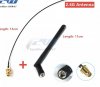
Attach antenna to coax.
Cut the other end off with a sharp razor trying not to crush the Teflon(?) inner insulator.
strip the outer plastic outer sheath back about an inch. Try not to nick outer copper braid.
strip 1/2 + inch or so from inner insulator to bare the copper center conductor. Did I mention try not to NICK the inner conductor.

Up above I did the math for a 1/4 wave length antenna hence you have made a 1/4 RF probe to find the source or where
you might solder the coax to. I trust you have a 5GHz scanner ( ;)).

Separate the PTZ away from the router/ cellphone /RF scanner and take a signal strength reading. Here
you would like a marginal signal so that when we place the probe close to the square internal antenna,
we will see a difference.

Time to probe! Mount antenna securely away from test bench in the open. Remember just about everything .516 inches and
odd multiple wave lengths are antennas (Radar Chaff). You might get enough gain from the external antenna to not have to
solder it just get it real close.
 
Top