HELP ! Bogen Apmlifier

c hris527

Known around here
Joined
Oct 12, 2015
Messages
1,793
Reaction score
2,090
Location
NY
Hi Folks,

I know this might be off topic and in the automation form but I was given a task of figuring out a Paging system. If anybody out there can help me with some questions that would be great. To the Mods, if you think it should be moved, please do so. I figure security installers out there have dealt with one of these systems before, thanks in advance for any help.

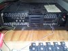
I have a large shop with a BOGEN TPU 100B paging system, I know nothing about them other than what I believe two of the runs stopped working. All the speaker wires come together in a closet and are labled. And all runs are twisted together, I have a ground, a white and black. I undid them and checked them and all seem ok at this end.

wires.jpg

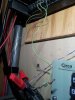
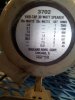
It is wired for 24V according to the bottom and triggered by the phone system. (Not sure if its ac or dc) I assume DC ? My book does not say. I know with a volt meter on DC I have zero volts and when triggered by paging I might be getting 1 to 2 Volts. Half of the shop works, the other are dead.

wires.jpg box.jpg

From what i have read from the manual, they considered a 24v Self Amplified system and outside power is supplied someplace in the run to power the speakers. Should I be looking for a transformer powering those runs considering 3 other runs are working? All the wires are tied together so it is acting like a all call. The dead runs are 20' up in the air and I will not have access to a man lift til later to check what i have up there. I Am just probing for some advice before I really get into it.
 

looney2ns

IPCT Contributor
Joined
Sep 25, 2016
Messages
15,606
Reaction score
22,832
Location
Evansville, In. USA
Yeah, I'd be looking for a transformer in the lines, and also the the non-working runs for rodent or other damage.
Transformers could be at each speaker. Unusual for them to go bad. But lightning can do strange things.
 

c hris527

Known around here
Joined
Oct 12, 2015
Messages
1,793
Reaction score
2,090
Location
NY
I will be taking a good look at a working one this afternoon, You would think these would run in parallel so if one get wacked it does not take out the chain, I did open a ceiling tile and saw the wires come in and go to the next but i did not open it up yet.
 

tangent

IPCT Contributor
Joined
May 12, 2016
Messages
4,421
Reaction score
3,654
I like it "CAUTION... DON'T ASSUME ANYTHING"

Can't say I've really tinkered with one of these. But lets cover some basics.

In a typical speaker and amp set up the impedance of the speaker needs to match the impedance of the amplifier to achieve maximum power transfer and prevent situations that could damage the amp. Typical speakers are 8 ohm or 16 ohm, it is possible to combine multiple speakers in parallel or series. This changes the impedance the amplifier sees (eg. two 16 ohm speakers in parallel = 8 ohms). On a small scale this works fine, but if you think about trying to put a bunch of speakers in varying combinations of series and parallel it turns into a real mess.

So paging systems typically operate at higher/fixed voltages and either have amplifiers built in to each speaker or a matching transformer.

As for troubleshooting a system like this, I'd probably bust out the oscilloscope if a few quick checks with a multimeter don't get the job done. And I'd look at the speakers closely. Looks like the speakers are probably 4 terminal, +/- 24VDC and tip/ring audio, check what you see at the speakers. The output from the amp will not be DC and will fluctuate with the audio signal. You could supply a sine wave input if you wanted.

Looks like there's lots of info here:
Bogen Learning Library
 
Last edited:

c hris527

Known around here
Joined
Oct 12, 2015
Messages
1,793
Reaction score
2,090
Location
NY
Thanks Guys, I disconnected the dead runs from the bunch, I put a toner on the runs and then I was like WTF..I saw somebody had taped into one of the runs and added another speaker. I at least have some sort of continuity through the system and I got to map out what speakers were on what runs..Its a start. Thanks for the Input. Tomorrow is another day . BTW I opened up and looked at a working ceiling speaker, The speaker did in fact have a transformer on it and I saw it could be wired for 24 or 70V .
 

tangent

IPCT Contributor
Joined
May 12, 2016
Messages
4,421
Reaction score
3,654
Thanks Guys, I disconnected the dead runs from the bunch, I put a toner on the runs and then I was like WTF..I saw somebody had taped into one of the runs and added another speaker. I at least have some sort of continuity through the system and I got to map out what speakers were on what runs..Its a start. Thanks for the Input. Tomorrow is another day . BTW I opened up and looked at a working ceiling speaker, The speaker did in fact have a transformer on it and I saw it could be wired for 24 or 70V .
From the little bit I looked up, it looks like the 24v ones are typically 4 wires per speaker with a power source and 70v systems are typically just 2 wires to the speakers. Also sounds like 70v is supposed to be more desirable.

Not sure about their choice of wire from the amp to the speaker wires. I'd probably use something like a terminal block rather than twisting the wires together / using wire nuts.

A photo of the setup from a bit farther back may be helpful.
 

c hris527

Known around here
Joined
Oct 12, 2015
Messages
1,793
Reaction score
2,090
Location
NY
You are correct about the 70V being a 4 wire tap, I did pull one down on a working run and did some voltage tests. The speaker had 2 different options to tap it and since the Amp is wired for 24, this was also. As I stated before I know ZERO about these systems. What Iam trying to get my head around is the voltages going from the AMP to the cluster of speakers when it is activated. It says its a 24v system but I have barely a volt on my meter when it is activated. It fluctuates slightly depending voice strengths. The run that is not working are Horn's, I took the first one down and tied the two wires together, then went back down to where they come home to the amp. I have continuity and almost 19 OHMS. A generous guess is that run is 100' so since i tied the wires together that 200' of 18gauge stranded speaker wire. 19 ohms to me seems a bit steep. I looked at some wire resistance charts and from what I have seen is telling me thats a lot of resistance in that run.
I also tested the resistance in the horn itself.
20170908_150839.jpg From the chart it seems correct if Im reading it right, there is 7 horns on this run @ 24v, The Ohms 43 through the speaker. That is as far as I got. Correct me on any of my Ideas so far.
Thanks
Chris
 

tangent

IPCT Contributor
Joined
May 12, 2016
Messages
4,421
Reaction score
3,654
You are correct about the 70V being a 4 wire tap, I did pull one down on a working run and did some voltage tests. The speaker had 2 different options to tap it and since the Amp is wired for 24, this was also. As I stated before I know ZERO about these systems. What Iam trying to get my head around is the voltages going from the AMP to the cluster of speakers when it is activated. It says its a 24v system but I have barely a volt on my meter when it is activated. It fluctuates slightly depending voice strengths. The run that is not working are Horn's, I took the first one down and tied the two wires together, then went back down to where they come home to the amp. I have continuity and almost 19 OHMS. A generous guess is that run is 100' so since i tied the wires together that 200' of 18gauge stranded speaker wire. 19 ohms to me seems a bit steep. I looked at some wire resistance charts and from what I have seen is telling me thats a lot of resistance in that run.
I also tested the resistance in the horn itself.
View attachment 21586 From the chart it seems correct if Im reading it right, there is 7 horns on this run @ 24v, The Ohms 43 through the speaker. That is as far as I got. Correct me on any of my Ideas so far.
Thanks
Chris
From the learning library link above:
https://www.bogen.com/support/productcatalog/pdfs/SysDsgn.pdf
https://www.bogen.com/support/pdfs/Installs.pdf

resistance != impedance
 

c hris527

Known around here
Joined
Oct 12, 2015
Messages
1,793
Reaction score
2,090
Location
NY
Thanks, I read up and it clears the air on this systems workings. Somebody added another horn last year to the already taxed system about a year ago. And then i find out they added another horn another run about 2 years ago without consideration of the power amp rating. This can make a good case for a degraded power amp. At this point, i will try a bypass cable to the first speaker in line on the bad run. We will see what happens. thanks for your help.
 

c hris527

Known around here
Joined
Oct 12, 2015
Messages
1,793
Reaction score
2,090
Location
NY
UPDATE: :lol: My gut feeling about the wiring rang true, I tested the horn speaker and all was fine, I then ran a jumper from the closet to the beginning of the first speaker. All worked, thanks guys for the help.

Chris
 

bob2701

Getting comfortable
Joined
Jan 7, 2016
Messages
1,009
Reaction score
482
Location
Jersey Shore
With a system like this the main problem you will run into is the wiring. If you make sure the wiring is good and it should be a minimum of 16ga, then all you need to do is make sure the transformer at the speaker (and each speaker needs a transformer) is matching the output line. Either 25 or 70 volts. You set the master gain on amp to provide the audio to the loudest area and then use the transformer in each speaker to adjust for it's area. On the picture of the horn you showed you can see the settings. Add up all the settings and make sure the overall is within the 100 Watts the amp provides.
 

tangent

IPCT Contributor
Joined
May 12, 2016
Messages
4,421
Reaction score
3,654
UPDATE: :lol: My gut feeling about the wiring rang true, I tested the horn speaker and all was fine, I then ran a jumper from the closet to the beginning of the first speaker. All worked, thanks guys for the help.

Chris
From pics it looks like the wire from the amp may be smaller than what it connects to. If that's the case that should also be fixed.
 

c hris527

Known around here
Joined
Oct 12, 2015
Messages
1,793
Reaction score
2,090
Location
NY
From pics it looks like the wire from the amp may be smaller than what it connects to. If that's the case that should also be fixed.
Ha Ha ha , that was the first thing I noticed, they recently had a new phone system installed, The company doing the install used basically 23gauge wire to run to the speaker cluster from the AMP. I'm usually the last call before they call in a contractor. I changed that out. Thanks again for the help.
 

looney2ns

IPCT Contributor
Joined
Sep 25, 2016
Messages
15,606
Reaction score
22,832
Location
Evansville, In. USA
I know of couple of (way overworked) IT types that work in local schools. The short story is, lots of contractors are terrible.
 
Top