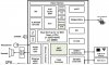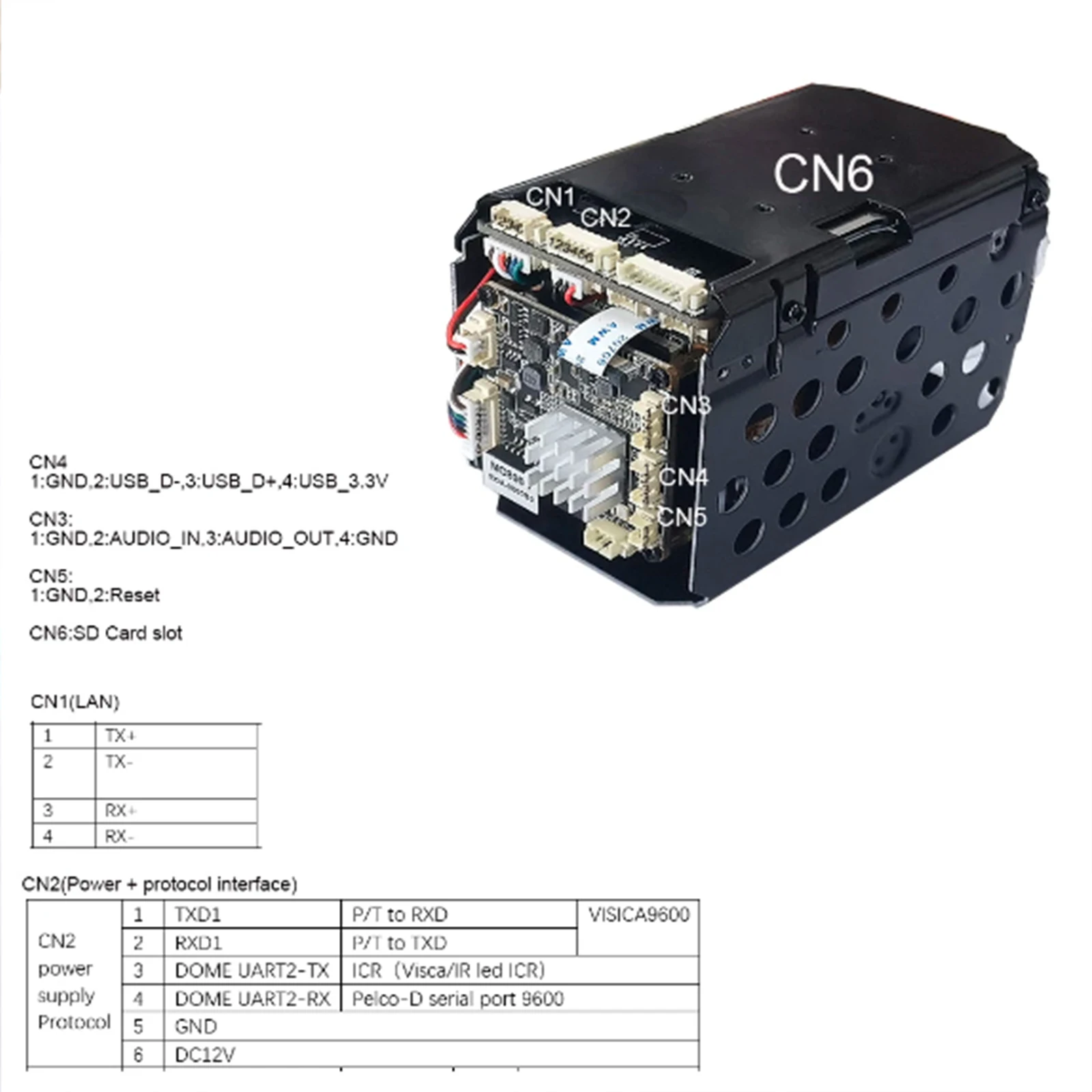

Forgive my ignorance here, but I've got these diagrams for a module I have. I'm trying to dump a copy of the internal Linux and make backup copies of the MTD files. I've tried to Telnet but cannot seem to crack the password. So I'm attempting to try doing it with a serial connection (USB to UART/TTL/RS485/RS232 adapter). Though these diagrams are quite sloppy, for lack of better words, It seems I'm able to make out on port CN2 (top middle) that pins 1 and 2 is transmit and receive for UART1 and pins 3 and 4 are for UART2...Those UART2 wires are connected to a Pelco-D pan/tilt bracket (RS485; Baud: 9600) and it pans and tilts on command as expected. Checking these pins against the ground with a tester gives 3.3v...My question is, should I be able to connect my USB adapter to these UART ports to access the camera's internal flash? I gave it a try on both the UART1 and the UART2 pins and connected with Putty, but all I get is a bunch of illegible characters...The characters do briefly change a bit when I click one of the pan/tilt buttons on the cam's web user interface, so I assume I'm just seeing an ASCII translation stream of the Hex Pelco-D commands...
I'm just wondering if this is the type of UART port that I'm looking for, or is this some special type of UART port that's only for sending/receiving Pelco commands? If it should work, any advice on how to get to a usable command prompt instead of a constant stream of unreadable characters (I've tried reversing pins, different baud rates, shorting the TX/RX pins on start up, etc and it doesn't help)..If these are special ports and not the UART that I'm looking for, any tips on where I may be able to find the correct one?
Thanks for any help! I'm a rookie at this stuff and this particular cam has proven to be a pain in the rear to "hack" into.