
randytsuch
Pulling my weight
- Joined
- Oct 1, 2016
- Messages
- 495
- Reaction score
- 176
Posting this to describe how I implemented simple, port based VLANs.
I have wanted to add VLANs to isolate my cameras from everything else, but have been putting it off because I thought it would be complicated. Turns out it was easy. Also, I did it all within one managed POE switch. This worked because I have all my cameras, BI PC and router connected to this switch. My asus router does not support VLANs, as far as I can tell.
I have a Luxul XMS-1008P switch, bought from ebay because the price was right. It is an older obsolete 8 port managed model. Its POE (not POE+), but is well built, and does everything I could want.
This switch supports Port and 802.1Q VLAN modes. I used Port VLAN mode because it was easier. I’m sure 802.1Q would work too, and give you more options, but that’s also more stuff to mess up.
I know just enough to be dangerous, so don’t expect a lot of technical information here, this is intended more as a practical how to post.
But just a little background, on why would you want VLANs. VLANs create separate little networks, but without needing to actually make separate little networks. So I can make a VLAN for my cameras and PC, and another VLAN for PC and router. This keeps the cameras isolated from the router. But it lets the PC talk to the cameras, and the router. OK, so now on to the details.
The ports on the Luxul switch are connected as follows:
Port Device
1 Main ASUS router
2 Blue Iris PC
3 Camera 1
4 spare
5 Camera 2
6 Camera 3
7 Camera 4
8 Spare
I went to my luxul switch web page, 192.168.1.xxx, where xxx is the address of the switch on your network. Logged into switch. Any managed switch will have a web interface, which is how you setup and monitor the switch.
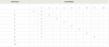
I went to the VLAN setup page, selected port VLAN, and then setup. With my luxul switch, you just select the VLAN Group number from a dropdown list, check the little boxes for the VLAN member ports you want to include in that VLAN, and then select Apply.
After you hit apply, the updated group will show up in the VLAN Group table.
I setup my VLANS as follows:
VLAN 1 = port 1 (router) and port 2 (BI PC). This lets my PC talk to the router, and via the router the internet and the rest of my network. To do this, you obviously need to have your router connected to your managed switch.
VLAN2 = port 2, 3, 4, 5, 6, 7 and 8. This creates a VLAN of the BI PC and all of my cameras. So now the cameras can talk to each other and the PC, but nothing else. The cameras cannot talk to the router, because the router is not part of VLAN2. So security wise, the cameras cannot talk to the internet, and even if someone were to break into your network, they could not talk to the cameras. The PC can talk to the router, because of VLAN1. Ports 4 and 8 are spares and could have been left out, but if you include and add a camera later to these ports, you don’t need to change anything.
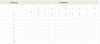
This is shown in the 2nd picture below.
Before I did this, I could see all of my cameras on my router’s client list. After I applied these vlans, and the list refreshed, the cameras were no longer there. Also, after I applied VLANS, I could not access any camera from my laptop. Before I did this, I could.
And that’s all I had to do to create two VLANs which let the PC talk to the internet and cameras, but keep the cameras off of the internet.
So now what if you want to get at a camera from your laptop? Go log back into the switch, and go back to the VLAN setup page.
Change VLAN2 to port 1, 2, 3, 4, 5, 6, 7 and 8
By including port 1 (router) in VLAN2, you can get at the cameras from any PC in your network, and from the internet.
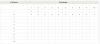
This is shown in the first picture below
Just remember to change back when you’re done, so your cameras will be isolated again.
You could also make a VLAN group for each camera, my switch supports up to 10 VLAN groups.
So you could have
VLAN 1 = port 1 (router) and port 2 (BI PC).
VLAN2 = port 2 and 3 This creates a VLAN of the BI PC and 1st camera
VLAN3 = port 2 and 4 This creates a VLAN of the BI PC and 2nd camera
VLAN4 = port 2 and 5 This creates a VLAN of the BI PC and 3rd camera
Etc
With this setup, the camaras can only talk to the BI PC, they can’t even talk to each other.
This is setup for VLANs to talk to internet and network. Port 1 (router) is part of VLAN2
This is normal setup, where VLAN2 is isolated from the internet, and your network except for one PC. Port 1 is NOT part of VLAN2
I have wanted to add VLANs to isolate my cameras from everything else, but have been putting it off because I thought it would be complicated. Turns out it was easy. Also, I did it all within one managed POE switch. This worked because I have all my cameras, BI PC and router connected to this switch. My asus router does not support VLANs, as far as I can tell.
I have a Luxul XMS-1008P switch, bought from ebay because the price was right. It is an older obsolete 8 port managed model. Its POE (not POE+), but is well built, and does everything I could want.
This switch supports Port and 802.1Q VLAN modes. I used Port VLAN mode because it was easier. I’m sure 802.1Q would work too, and give you more options, but that’s also more stuff to mess up.
I know just enough to be dangerous, so don’t expect a lot of technical information here, this is intended more as a practical how to post.
But just a little background, on why would you want VLANs. VLANs create separate little networks, but without needing to actually make separate little networks. So I can make a VLAN for my cameras and PC, and another VLAN for PC and router. This keeps the cameras isolated from the router. But it lets the PC talk to the cameras, and the router. OK, so now on to the details.
The ports on the Luxul switch are connected as follows:
Port Device
1 Main ASUS router
2 Blue Iris PC
3 Camera 1
4 spare
5 Camera 2
6 Camera 3
7 Camera 4
8 Spare
I went to my luxul switch web page, 192.168.1.xxx, where xxx is the address of the switch on your network. Logged into switch. Any managed switch will have a web interface, which is how you setup and monitor the switch.
I went to the VLAN setup page, selected port VLAN, and then setup. With my luxul switch, you just select the VLAN Group number from a dropdown list, check the little boxes for the VLAN member ports you want to include in that VLAN, and then select Apply.
After you hit apply, the updated group will show up in the VLAN Group table.
I setup my VLANS as follows:
VLAN 1 = port 1 (router) and port 2 (BI PC). This lets my PC talk to the router, and via the router the internet and the rest of my network. To do this, you obviously need to have your router connected to your managed switch.
VLAN2 = port 2, 3, 4, 5, 6, 7 and 8. This creates a VLAN of the BI PC and all of my cameras. So now the cameras can talk to each other and the PC, but nothing else. The cameras cannot talk to the router, because the router is not part of VLAN2. So security wise, the cameras cannot talk to the internet, and even if someone were to break into your network, they could not talk to the cameras. The PC can talk to the router, because of VLAN1. Ports 4 and 8 are spares and could have been left out, but if you include and add a camera later to these ports, you don’t need to change anything.
This is shown in the 2nd picture below.
Before I did this, I could see all of my cameras on my router’s client list. After I applied these vlans, and the list refreshed, the cameras were no longer there. Also, after I applied VLANS, I could not access any camera from my laptop. Before I did this, I could.
And that’s all I had to do to create two VLANs which let the PC talk to the internet and cameras, but keep the cameras off of the internet.
So now what if you want to get at a camera from your laptop? Go log back into the switch, and go back to the VLAN setup page.
Change VLAN2 to port 1, 2, 3, 4, 5, 6, 7 and 8
By including port 1 (router) in VLAN2, you can get at the cameras from any PC in your network, and from the internet.
This is shown in the first picture below
Just remember to change back when you’re done, so your cameras will be isolated again.
You could also make a VLAN group for each camera, my switch supports up to 10 VLAN groups.
So you could have
VLAN 1 = port 1 (router) and port 2 (BI PC).
VLAN2 = port 2 and 3 This creates a VLAN of the BI PC and 1st camera
VLAN3 = port 2 and 4 This creates a VLAN of the BI PC and 2nd camera
VLAN4 = port 2 and 5 This creates a VLAN of the BI PC and 3rd camera
Etc
With this setup, the camaras can only talk to the BI PC, they can’t even talk to each other.
This is setup for VLANs to talk to internet and network. Port 1 (router) is part of VLAN2
This is normal setup, where VLAN2 is isolated from the internet, and your network except for one PC. Port 1 is NOT part of VLAN2
Last edited:
")