
sebastiantombs
Known around here
After a terrible experience with an EZViz DB1C I had to find something better. I really wanted something with PoE and Dahua came out with the VT)2231R-WP, both 12vdc wireless and PoE. While it's certainly not a high resolution camera for the purposes of a doorbell, which is an up close and personal view, it should be just fine. So I ordered one from Andy and it came quickly (thanks Andy!). My next problem was to get it to work with a mechanical chime. I converted a VTO2201 to do that and proceeded on the assumption that the same technique would work for this one. I know I could probably grab some packets and use them to trigger an external relay but coding isn't my strong suit so I opt for more direct and simple methods.
If you are not skilled with a soldering iron and do not have a good temperature controlled station I would not recommend attempting this modification. Everything is SMD, surface mounted, and the boards are fairly dense with components. Even with a temperature controlled station, drop the heat back to 500-550, depending on your solder, to minimize any possibility of heat damage. Of course, neatness is vital so don't gob the solder on. Just tin the wire, clean and tin/wet the tip with a little solder and tack the wire in place.
My assumption is that when the button on the doorbell is pressed one side of that switch will go "low". If a high impedance voltage sensing relay is attached to that side of the switch an isolated normally open contact set is provided. The trick is to get inside the doorbell to be able to tack on a lead.
There are six screws holding the case of the 2231R together. Remove them. Then pull apart the case. The boards are attached to the front half of the case. Once the back is off you'll see the two boards. The main, or lower board with PoE, network and sound on it, and the upper board that is the camera. There are three plug-in leads on the camera board that need to be unplugged to get that board far enough out of the way to remove the main board. Unplug them carefully. They will remain in the correct orientation to make re-assembly easy. There are three black phillips head screws holding the camera board in place, so remove them. Pull the board straight up from the body to remove it. Pulling straight up is important because the camera projects through a rubber grommet at the lens and there is a high density, multi-pin, connector to supply connection to the PoE/network board. Move the camera board out of the way.
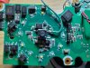
There are a couple of more two-wire connectors that need to be unplugged from the main board. Again, they will maintain their positions well enough that re-assembly is not problem. There are two really small ones that I didn't unplug, deliberately, because my fingers are too big. There are three more black phillips head screws holding the main board in place so remove them. One of them is up at the top where the camera board would cover it if that board isn't removed. Carefully lift the main board and flip it over so you can see the switch. There are four pads on the switch and you can see which pad I picked to attach a lead for the voltage sensing relay. Carefully tack a lead onto that pad.
Re-assemble in reverse order and make sure no wires are pinched in the process. Be careful when seating the camera board and make sure the high density connector is properly aligned before seating it fully. When I put the case back together I found a nice little hole adjacent to the cutout for the external wiring connector and passed my extra lead through that hole. Button it all up and you're good to go. There are two ground leads coming off the external wiring plug and either one will work for the voltage sensing relay. The biggest trick is wire management when mounting the doorbell.
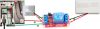
I remoted the voltage sensing relay and am powering it with a USB wall wart. I bought these a while ago, anticipating a need like this. They are not available any longer but will give you an idea of what to use. The trick is the opto coupler for a really high input impedance, minimal loading.
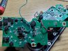
Here's and overview after tacking in the extra lead. The camera board is in the background here -
Here's a close up showing the pad I attached to more clearly -
If you are not skilled with a soldering iron and do not have a good temperature controlled station I would not recommend attempting this modification. Everything is SMD, surface mounted, and the boards are fairly dense with components. Even with a temperature controlled station, drop the heat back to 500-550, depending on your solder, to minimize any possibility of heat damage. Of course, neatness is vital so don't gob the solder on. Just tin the wire, clean and tin/wet the tip with a little solder and tack the wire in place.
My assumption is that when the button on the doorbell is pressed one side of that switch will go "low". If a high impedance voltage sensing relay is attached to that side of the switch an isolated normally open contact set is provided. The trick is to get inside the doorbell to be able to tack on a lead.
There are six screws holding the case of the 2231R together. Remove them. Then pull apart the case. The boards are attached to the front half of the case. Once the back is off you'll see the two boards. The main, or lower board with PoE, network and sound on it, and the upper board that is the camera. There are three plug-in leads on the camera board that need to be unplugged to get that board far enough out of the way to remove the main board. Unplug them carefully. They will remain in the correct orientation to make re-assembly easy. There are three black phillips head screws holding the camera board in place, so remove them. Pull the board straight up from the body to remove it. Pulling straight up is important because the camera projects through a rubber grommet at the lens and there is a high density, multi-pin, connector to supply connection to the PoE/network board. Move the camera board out of the way.
There are a couple of more two-wire connectors that need to be unplugged from the main board. Again, they will maintain their positions well enough that re-assembly is not problem. There are two really small ones that I didn't unplug, deliberately, because my fingers are too big. There are three more black phillips head screws holding the main board in place so remove them. One of them is up at the top where the camera board would cover it if that board isn't removed. Carefully lift the main board and flip it over so you can see the switch. There are four pads on the switch and you can see which pad I picked to attach a lead for the voltage sensing relay. Carefully tack a lead onto that pad.
Re-assemble in reverse order and make sure no wires are pinched in the process. Be careful when seating the camera board and make sure the high density connector is properly aligned before seating it fully. When I put the case back together I found a nice little hole adjacent to the cutout for the external wiring connector and passed my extra lead through that hole. Button it all up and you're good to go. There are two ground leads coming off the external wiring plug and either one will work for the voltage sensing relay. The biggest trick is wire management when mounting the doorbell.
I remoted the voltage sensing relay and am powering it with a USB wall wart. I bought these a while ago, anticipating a need like this. They are not available any longer but will give you an idea of what to use. The trick is the opto coupler for a really high input impedance, minimal loading.
Here's and overview after tacking in the extra lead. The camera board is in the background here -
Here's a close up showing the pad I attached to more clearly -
Last edited:
As an Amazon Associate IPCamTalk earns from qualifying purchases.
")