AXIS P55/Q60 Multi-connector cable - pinout?

Sinusvag

n3wb
Joined
Sep 9, 2024
Messages
7
Reaction score
0
Location
Sweden
Hi all,

So, I am the new happy owner of an old P5534 PTZ camera. This camera will be used to watch birds and provide some basic oversight in a small cabin in the woods in the South of Sweden.

To power the camera, I ordered a cheapo POE Switch from Ali, and - as can be expected, the camera webserver proclaims that the camera hasn't enough power for the PTZ and camera to work. So, my plan is to run the camera from a 24V DC power supply. According to the Axis manual, there is a special cable 5502-491 that apparently contains a multitude of I/O, among them 24V DC and AC in. Trouble is that Axis has not provided the pinout for the actual connector in the camera. Dotworkz has a small patch cable for their enclosures that should do the trick, but it feels like overkill to buy this one since I have a soldering station 1 meter from where I am sitting.

So here the question goes: does anyone have a clue about the pinout used in the internal connector for the P55/Q60 cameras?

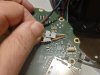
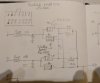
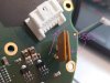
I have a hunch that two pins that are internally connected in series with fuses could be the suspects to use for 24V DC in, but perhaps I am mistaken here (see pic).

Any info would be greatly appreciated!

DSC_8713__.JPG
 

Lehrian

n3wb
Joined
Sep 16, 2024
Messages
9
Reaction score
1
Location
USA
Did you ever get or figure out the pin out? I'm trying to connect a microphone to one of these ports. You probably already know but the mating connector is a Molex Mfr. #: 51353-1400 and the pins are Mfr. #: 56134-9100.
 

Sinusvag

n3wb
Joined
Sep 9, 2024
Messages
7
Reaction score
0
Location
Sweden
Hi Lehrian,

Actually yes and no. I traced the PCB and came to the conclusion that the two pins marked in the first post are for 24V AC (after the fuses, the traces lead to a bridge rectifier circuit). In my case, I had readily available access to 19V DC (an old Dell charger), and figured that positive goes to either of the two pins in the first pic, and negative to a grounded pin. See pic below. Works perfectly, no need for 24V.

As for the Audio IN, no info. (I would guess that that input pin should lead to a capacitor, but I did not investigate the matter).

But, there are many knowledgeable people on these boards, so let's keep our fingers crossed that some pro can spend 5 mins with an old 5502-491 cable and tell us more.DSC_8718_small.JPG
 

Lehrian

n3wb
Joined
Sep 16, 2024
Messages
9
Reaction score
1
Location
USA
Thanks for the reply. Can you tell me which 2 pins on the connector the power pins are? That will eliminate two more pins from my searching. I have already identified 2 ground and 2 x 3.3v so with these two that will drop me down to 8 possible pins.
 

Sinusvag

n3wb
Joined
Sep 9, 2024
Messages
7
Reaction score
0
Location
Sweden
OK, looking at the
  • white male connector
  • from the outside of the camera enclosure
  • noting the small cutout in the connector
the power pins are (my numbering, not sure if it is Molex standard for this connector).

If you have more info, please fill in the blanks!

CUT--------------------------OUT-----------------
1 24VAC in no 1, or DC+ 24V2 24VAC in no 2, or DC+ 24V3 ---4. ---5. ---6 ---7 ---
8 DC- (GND)9 ---10 ---11 ---12 ---13 ---14 ---

Edit: That table came out not so good, see my own schematic for further reference below:
DSC_8749_small.JPG
 
Last edited:

Lehrian

n3wb
Joined
Sep 16, 2024
Messages
9
Reaction score
1
Location
USA
11 and 12 are at 3.25 V and 14 is at GND. I am waiting on the connector to be able to test the ones on the top row as I can't reach them with my probes. I'm looking for the Mic in and as long as the pins don't have voltage on them I can hook them to the microphone without worrying about damaging it. And obviously any pins that are GND aren't the ones I'm looking for either. We have a P5534 that has failed and we tried to replace it with a newer model camera but the network cable isn't supporting the 1GB network connection (it's installed underwater believe it or not!) So while we figure out the networking issue (pulling a new cable isn't simple) we have obtained new "old stock" of the P5534 and are hooking it back up. Unfortunately the new camera used a different connector for the mic and we cut the wires to the old connector without marking them...doh!
 

Sinusvag

n3wb
Joined
Sep 9, 2024
Messages
7
Reaction score
0
Location
Sweden
Lehrian,

Interesting to hear about an underwater ip camera! ROV?

My advice: Just power off the cam and open it - just a few screws to get to the PCB and from there you can probe it. Also, it is simple to add a temporary connection using some wires from a network cable to a mic and power the cam up carefully whilst taken apart (just make sure not to hinder the servos driving the PTZ).

Updated the table:

CUT--------------------------OUT-----------------
1 24VAC in no 1, or DC+ 24V2 24VAC in no 2, or DC+ 24V3 ---4. ---5. ---6 ---7 ---
8 DC- (GND)9 ---10 ---11 3.3V12 3.3V13 ---14 GND
 

Lehrian

n3wb
Joined
Sep 16, 2024
Messages
9
Reaction score
1
Location
USA
Looking at the camera and there are 4 configurable ports. They can be configured for input or output and can be left as open circuit or GND. So it looks like I can eliminate 4 more pins by setting these to output and GND and then finding them. So that is 10 of the 14 pins and there is a audio in and out so that is the last 4 pins. This shouldn't be too difficult once I get the connector.
 

Sinusvag

n3wb
Joined
Sep 9, 2024
Messages
7
Reaction score
0
Location
Sweden
Nice! Yeah, I think that would be the right strategy. Do keep me posted on your findings!
 

Lehrian

n3wb
Joined
Sep 16, 2024
Messages
9
Reaction score
1
Location
USA
So it looks like pins 11 and 12 are actually the audio input. I was playing around with setting the ports to GND and testing the pins and noticed that pins 11 and 12 no longer had any voltage on them. I set all the ports back to input - floating and they still had no voltage on them. That is when I realized that I also switched off Mic power. I switched Mic power back on and pins 11 and 12 went back to 3.25v. So they are the Mic pins I'm looking for.
 

Lehrian

n3wb
Joined
Sep 16, 2024
Messages
9
Reaction score
1
Location
USA
Alrighty...so here is what I have determined. 3 - IO Port 4, 4 - IO Port 3, 5 - IO Port 2, 6 - IO Port 1, 7 - 3.3v power, 8 - GND, 9 & 10 are audio output, 11 - mic in, 12 - line in, 13 don't know, seems to float, may not be connected, 14 GND
 

Lehrian

n3wb
Joined
Sep 16, 2024
Messages
9
Reaction score
1
Location
USA
And I'm guessing that pin 14 is probably signal ground, though it may be tied to power ground, I dunno. I'm using pin 14 as GND for the mic. I didn't want to tear it apart and try to follow the traces.
 

Sinusvag

n3wb
Joined
Sep 9, 2024
Messages
7
Reaction score
0
Location
Sweden
And I'm guessing that pin 14 is probably signal ground, though it may be tied to power ground, I dunno. I'm using pin 14 as GND for the mic. I didn't want to tear it apart and try to follow the traces.
Updated the table!

CUT--------------------------OUT-----------------
1 24VAC in no 1, or DC+ 24V2 24VAC in no 2, or DC+ 24V3 I/O port #44. I/O port #35. I/O port #26 I/O port #17 3.3V power
8 DC- (GND)9 AUDIO OUT #110 AUDIO OUT #211 3.3V MIC IN12 3.3V LINE IN13 ---14 GND
 

Lehrian

n3wb
Joined
Sep 16, 2024
Messages
9
Reaction score
1
Location
USA
Updated the table!

CUT--------------------------OUT-----------------
1 24VAC in no 1, or DC+ 24V2 24VAC in no 2, or DC+ 24V3 I/O port #44. I/O port #35. I/O port #26 I/O port #17 3.3V power
8 DC- (GND)9 AUDIO OUT #110 AUDIO OUT #211 3.3V MIC IN12 3.3V LINE IN13 ---14 GND
My only comment is that MIC IN and LINE IN are only 3.3v when the option "Microphone power " in the camera under "Audio Settings" is checked and saved. Otherwise it is GND.
 
Top