Documenting the Construction of My Rural IP Camera System

Tim Swift

Getting the hang of it
Oct 22, 2023
8
35
Tennessee
I’m working on building a camera system for a large rural property, and will do my best to document the process in this thread for those who might be interested. Should be fun! Also, this is my first post to the form, and I wanted to say thank you to all the people who have shared their knowledge on this topic. Very helpful.

I’m going to start at the beginning with the project goals, and then move onto some specifics of the property, and the challenges those bring. Right now, I’m still planning and testing, anything here could change if it turns out to be suboptimal!

To understand the below discussions, the property is mostly wooded and has a public roadway along the border.

The project goals, listed with highest priority first:
  • Detection – Alerting us humans of a problem.
  • Monitoring – General awareness of what’s going on.
  • Documenting – This one is pretty ubiquitous.

Detection:

Think driveway alarm. This is the primary goal, to know when something happens so that it can be addressed in real time, instead of investigated later. Now, there is a point of contention that a separate alarm system should be used for this, and in the case of a suburban home, that very well may be correct. However, in a rural setting I’ve found that anything short of an imaging device with object detection does not cut it. Working on a dedicated sensor system would be interesting, but would involve a lot of custom work beyond my meager skill level.
Right now AI object detection in BI looks like the best option. Detection systems built into the cameras also appear promising from what I’ve read, but I still have a lot to learn. As time goes on, the detection systems available to BI will probably get even better, so I have high hopes.

Optimally, when something is detected, an alarm would sound, and a capture of the anomaly would be shown on a big screen for my sleepy eyes to see. Being able to reduce the severity of the alarm during the daytime in certain areas, such as the driveway, would minimize irritation during the day when there is a lot of legitimate activity. And while we’re at it, a big map with flashing lights would be nice as well…


Monitoring:

Pretty simple on the face of it. Having (several?) displays with the video feed from overview cams that let the situation be seen at a glance. The BI UI3 would also be very helpful for adding displays to other rooms or buildings. Having all the relevant feeds displayed clearly is important, so that the situation is easy to see without fiddling with the interface.
While we’re on the subject, it would be interesting to have a very low-level detection that would help with general awareness, such as capturing and displaying photos of cars or pedestrians that are approaching the property. Sort of an early warning. Not sure if this can be done in BI, or if it would even be helpful, but it would be fun. This low-level detection would also be handy during the day for high traffic areas, such as the drive way, same as mentioned in the above discussion of detection.


Documenting:

Same as every other system. Recording video for review later. While this is at the end of the list, as I think the above goals are more useful under my circumstances, recording is still essential. It’s one of those things I did not appreciate until I used it. There are many cases when skipping back ten minutes to see where something went helps resolve a real time situation. Not to mention collecting evidence for later.


The above lays out the general goals of the system. Now I’ll jump into a few more details that will give an opportunity to discuss many of the challenges. First, the layout of the property:

The road sharply bends, forming a ninety degree turn. The property is located on the inside of this bend, making it almost a corner lot, though there is no intersection. The driveway enters the road near the bend. The house is located further into the property, about 130 feet from the road and 250 feet from the entrance to the driveway. There is another building near the house, that I’ll probably have an network switch in. The property runs along the road in each direction from the bend for about 500 feet. Across the street, and around the area of the drive way entrance, there are a couple entrances to adjacent properties. Also, the entire perimeter If the property along the roadway is fenced and wooded inside of the fence. There are other features I’m sure I’ll discuss later, but this gives the general scope of the project.

I need to draw up a map ;)

The areas I’d like to cover:
  • Along the roadway, monitoring traffic on the road, and keeping an eye on the fence line.
  • The entrance to the drive way.
  • The entrances to the properties across the street.
There are a number of other areas that I’d like to cover, but those are outside of the scope for now. However, I should keep them in mind so as to leave plenty of room for expansion.

Covering the entrance to the driveway will take a couple cameras, one zoomed in shot showing a clear view of the entrance and anyone in it, and a wider angle camera to the side to capture an overview. Another couple cameras will be needed to cover the entrances across the street. So that makes four cameras all in the same area (the zoomed camera might be pretty far back though). This cluster is about 300 feet from the nearest building, and helps show some of the challenges.

Finding the best way to get data and power to each camera is what I need to figure out here. There are a few ways I can think of doing it:
  • Running a separate ethernet cable to each camera.
  • Running one ethernet cable and a 120 VAC line to power a switch.
  • Running one ethernet cable with PoE++ to power a passthrough switch.
  • Running fiber and 120 VAC.
  • Using a wireless bridge and running 120 VAC.
  • Using a wireless bridge and a solar power system.
The first option is expensive, and the only way to leave room for expansion is to run extra cables, or decide to use option three later on.

The second option is solid, and would leave a lot of power on the table for IR lights, etc. The AC wire would need to be in conduit, and this adds a bit of cost. It would also require a bit more care to keep the system safe.

The third option is attractive due to the simplicity. However, there is only one PoE passthrough switch I can find that fits the bill, the Intellinet IPS-05G-65W. It has five ports, and could connect to four cameras. That does not leave any room for expansion or powering IR lights. If there were more switch options that had more ports, this would probably be the go-to.

Running fiber and power is attractive, other than the cost and complexity of fiber. The attraction of this set up is the added resistance to lightning induced transients. However, I already have a lot of properly rated ethernet cable…

While using a wireless bridge is an option, I see no point if I already have to run power. Also, I prefer a hard connection if possible (don’t we all).

Going fully remote with a small solar system is both expensive, and would require a significant cleared area for the panels, which does not exist.

Which of these is best? I was leaning in the direction of option number three. While typing this I’ve realized the issues with only one 5 port PoE++ Passthrough switch being available for use. If there were larger PoE++ pass through switches available, that would change things. But until that happens, and it probably won't due to the Poe+ power budged getting too low, five ports is not going to be enough for future expansion. Running two cables and having two switches might be viable, but starts getting more costly.

Running a 120 VAC line and an ethernet line may be the best option. This would allow for any PoE+ switch to be used to add as many devices as desired, as well as additional power options.

Running a fiber cable along with 120 VAC is the last choice, and really comes down to how much concern there is with long copper runs and transients.

I’ll probably go over my concerns with lightning in the next update.
 
Lightning surges are a huge concern I have when running any long wires. In this post I’m going to try and explain why I have these concerns, and then try to figure out the best way to protect the system against damaging surges.

Here is a list of some of the damage I have seen done by lightning induced transients:
  • Three different modems and/or routers connected to the mostly buried 300 foot CAT3(?) telephone line. These failures were each about five years apart, and happened during bad thunder storms. The line is unshielded and no protection was installed. I’m honestly surprised how rare these failures have been, maybe due to the depth of the cable, more than a couple inches. The most resent was the worst, with blown SMT caps and a damaged DSL splitter.
  • Old (CRT) Radio Shack CCTV system. The one camera had a buried 200 foot coax / power combo cable. Damage was to the base unit, but never found out what exactly.
  • DIY driveway alarm running 5 volt signal lines over 200 feet of alarm wire. Several component failures. System was powered by 12 VDC.
  • Cheap analog over coax CCTV system. The video controller and several of the cams went out. System was powered by 12 VDC.
  • Nicer analog over twisted pair system. This system was powered by 48 VDC over one of the pairs with custom made 48 VDC to 12 VDC power boards at each camera, these boards had built in protection and were properly grounded. All cable was shielded CAT6, the shielding was grounded at the end of each run alongside the power board. After the strike the DVR, cameras, power boards, and 48 VDC supply where destroyed. One of the video baluns by the DVR was severely damaged, and is probably what allowed the surge into the DVR. The HDMI monitor connected to the DVR also failed. An important note about this system is that the CAT6 was run along the bottom of a steel wire fence, I believe this had much to do with the severity of the damage.
  • Pump controller. The pump controller is outdoors and fed 30 VDC from an indoor supply via a 100 foot two conductor cable. The controller failed to function after the surge, though exact damage is unknown.
The above list is to show the severity of the issue, we get plenty of thunderstorms here. An important point I’d like to touch on is what has not been damaged by lightning:
  • 200 foot 120 VAC run to an outbuilding. No 120 VAC powered device in this building has suffered damage, including a TV, Wi-Fi router, LED lighting, and computers.
  • 100 foot 240 VAC run to another outbuilding. No failures, even though the building is full of 3D printers, computers, paper printers, and networking gear.
  • 200 foot 120 VAC run to a third outbuilding, once again no failures, including... well, I think you get the point!
The above AC lines are buried 12” deep or greater. The only surge protection is located at the main panel at the house. The point is that buried 120 VAC lines are resistant to surges, or that modern switching power supplies are just that tough! Either way, running 120 VAC outdoors does not appear to be an issue.

The question is, how to run ethernet outdoors without inviting failure during the next heavy thunderstorm. On my analog of twisted pair system, I had issues despite using properly grounded shielded cable. This could have been for a few reasons, including:
  • Running the cable along the bottom of the fence rather than burying it.
  • Improper grounding or management of the 48 VDC system.
  • Analog camera gear that is still made is crappy and vulnerable.
The above three issues would be eliminated on a new install, but that does not mean there are not other vulnerabilities. On the new IP camera system, the runs that I am most concerned about are those that lead from the switch in the house, or a switch in an outbuilding, to the remote switch, as these will be the longer runs. The run from the remote switch to the camera will be a lot shorter, but could still be an issue. The long runs could be replaced by fiber, which should eliminate all issues. However, I would rather use the large stock of shielded CAT6 I have on hand.

This is the layout I have in mind: 120 VAC powering the remote switch (e.g., the one by the entrance to the driveway), shielded outdoor CAT6 cable providing data to the remote switch. The shielding would be grounded via a shielded keystone connector at the remote switch. From the keystone a shielded patch cable would lead to a surge protector, and then another patch cable would lead to the switch. The cables to the cameras would terminate in the same way, possible less the surge protectors. The surge protectors, and with them the shielding, will be grounded to earth. The shielding at the cameras and at the house switch would not be grounded. A few questions I still must answer:
  • Would surge protection at the camera be worthwhile? If so, then the shielding would most likely be grounded at the camera rather than the remote switch. The distance from the remote switch to the camera will likely determine the answer to this.
  • Should the 120 VAC system be grounded at the remote switch or share a ground with the house system via a grounding wire? The latter would be more in line with code, but the former is currently how our remote buildings are wired, each building having its own earth ground.
  • Will shielding and surge protection be enough to protect the switches and cameras? As far as I can tell, there is only one way to find out, problem is it could take several years to get the right storm. If the answer is no, then fiber becomes the only option.
Finding surge protection is another issue. As far as I have found, there are only a couple options:
  • The Ditek DTK-NETMS. This is a nice modular design that can be rack mounted or used in smaller sets. Only issue is they are $60 apiece.
  • The Ubiquiti ETH-SP-G2. These units are cheap, only $15 or so. Issue is they are bulkier, and would be harder to gang up for use with several data lines. Also, are they as effective as the Ditek units? The unit will be installed in an outdoor enclosure, so the nice case is not important.
At the end of the day, I have been unable to find much solid info on protection against lightning, and it looks like this is going to have to be an ongoing experiment. Any experience you have had with lightning damage, or the lack thereof, would be very interesting!
 
Last edited:
Such a great write up, it's disappointing not to see any replies. Do you have any updates as to how it's going?
Well, it's just my thoughts on the subject, so probably plenty of mistakes I've not learned about the hard way yet! I've had a failure on my Blue Iris PC which has set things back, trying to fix it before buying another. I did buy a 2MP turret camera from Andy, and am going to design some 3D printed mount / junction boxes for it, so that should be fun. Got several other projects going, so I have to move back and forth ;) Oh! I forget to mention, I did buy one of the Ubiquiti ETH-SP-G2 surge protectors and pulled the board out. It looks like it's only gas discharge protection, and no active components. Probably not that effective.
 
Got to love trying to monitor large properties. I have been trying to complete this task for the last 7 years, lol.. Ive ran into what I call, location, location, location, in which I have had to change camera locations to meet my goals of monitoring a 10ac area. Driveway over 300ft, several other point of entries (possible foot traffic), and love to watch the wildlife in the woods.
The biggest bumps I have yet to master are the POE switches. They are so hit and miss for the uplink ports capability, specs saying one thing to what they actually deliver. The one item I would suggest is to have a completely separate dedicated network for your surveillance. Vlans are nice, but nothing beats having true separation especially if you have limited knowledge of networking. Mind you I now have more then 40 cameras running always recording.
Networking cable is the next item. Even if you have conduits to run them in its best to use "direct burial" type cable, and make sure its solid copper, and use the largest gauge you can find, so 23AWG or lower (ps, critters, animals love to nibble on them). Cat6 has a lower distance ability compared to Cat5e. Max i can go with cat6 is around 260ft, where using cat5e I i pushed it to 700ft with good results.
As for external power runs, I have been testing out some POE switches that are powered by POE (they can also be used to extend the range of your camera deploys), in which there is a POE IN port that provides the uplink as well as the power required. I use POE injectors at the main switch to provide the power. You will also have to figure out voltage drops over the span of the cable length to make sure that you have the need power at the end of the cable to support the devices. I dont use high power cameras (like ptz ones) at locations of long runs. So far so good when it comes to continuous recording.
I do not use BlueIris, mainly because of it being a single point of failure, when that goes down I loose access to everything. I use Xpenology and synology surveillance station, actually 6 VMs of xpenology deployed with Proxmox and a product called CMS (Centralized Management System) to pool all the cameras into one location. So if I have an issue with 1 of those VMs, I only loose recordings from a small group of cameras. I am not sure if Blueirus has this ability or not. I then use another VM to complete any AI review to reduce the amount of false detections.
For my driveway I have 5 dedicated cameras, each for its own purpose. 1 mainly for early detection, 1 for LPR'ing, and the others for face detection and general detection. The other item I also use is a product called MULE, which detects anything metal coming down the driveway. I also use relays (triggers) to help provide confirmation that someone is here. So if the metal detector goes off, and 1 or more cameras are also triggered, then a warning is generated inside (beeping) and outside the house (strobe light). I am sure I have has some unwanted guests in the middle of the night come by and low and behold, when that strobe light goes off they high tail it out of there.

I still label myself as a newbie when it comes to such a deployment, and for what I have, I am always thinking of what else I could depoly.. lol
I am always learning something from IPCAMTALK users. :)
 
Last edited:
I do not use BlueIris, mainly because of it being a single point of failure, when that goes down I loose access to everything. I use Xpenology and synology surveillance station, actually 6 VMs of xpenology deployed with Proxmox and a product called CMS (Centralized Management System) to pool all the cameras into one location. So if I have an issue with 1 of those VMs, I only loose recordings from a small group of cameras. I am not sure if Blueirus has this ability or not. I then use another VM to complete any AI review to reduce the amount of false detections.
I've been thinking about the single POF issues when running a single BI machine, but alternative systems are pretty complex! I'll have to look into it, you have an interesting set up. I know BI has a manage function now where you can have several installation managed from a single machine, but I need to read up on it. I don't know how well it conglomerates the video for viewing and playback from each location.

The CAT6 vs. CAT5e is also interesting, I'll have to look what I have, but I think it's mostly CAT6.
 
  • Like
Reactions: mat200
"I've been thinking about the single POF issues when running a single BI machine"

I wonder if it is possible for Blue Iris to incorporate a Failover for people with multiple BI systems. I have no idea how hard or practical it is to do.

I asked You.com about Failover
"Conclusion
Failover in security systems is a backup operational mode that automatically switches to a standby system if the primary system fails or requires maintenance. It enhances reliability, ensures continuity during maintenance or failure, and provides safety and security. However, it's important to consider security measures, such as using firewalls, to protect against unauthorized access during failover."
 
Much time has passed, but I'm finally back on the IP camera system project! Here is a quick update on the 3D printed camera boxes I'll be using:

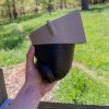
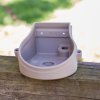
The enclosure is designed to be both a junction box and turret camera mount. I'm using the IPC-T54IR-ZE turret cam I bought through Andy's EmpireTech website. The camera is attached via three screws that thread into heat set inserts in the bottom of the box. The lid attaches via a couple of screws from above. I intend to mount the box to a 4 x 4 posts via sealing roofing screws. The cable will leave the box via a 1/2 inch conduit, which fits into a hole in the bottom of the box. This one is printed in PLA for testing, but I'll probably use PETG for the final boxes due to better weatherability.
Camera and box ready to mount.Camera box bottom.Camera box top.

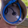
Below you can see the interior of the box with wires installed. I decided not to provide a mount for the keystone connector because there was not enough space unless the box was made substantially larger. There is just enough room to coil up all the wires inside and install the lid. You can also see the installed heat set inserts. The cable from the camera is sealed by a 3D printed TPU gland. The box should be bug proof ;)
Camera Box Wires.jpg

I'm sure I'll need to make some more changes, but once it's final if anyone is interested I'd be happy to share the files. I wonder how universal the hole pattern for turret cameras is? That's all for today!
 
The first sets of "trunk lines" have been installed. These run from the house out to the boxes that will house the PoE switches. I used a ditch witch for the trenches in the woods, and tried to keep it at least 12" deep. The 120 VAC was run in 1/2" PVC and the data cables in 1" PVC. Two data cables where run to each box even though only one is needed for the time being, this should insure options in the future.
Below is a photo of one of the boxes, the front cover is held on by magnets.
CCTV Wood Box.jpg

Trenching in the woods is not particularly easy due to the roots. Here you can see a particularly dense section.
Trench In Woods.jpg
Yesterday we got the first camera online, along with some lights. The lights are controlled via a Control by Web ethernet controlled relay. For the time being it is manually controlled by the web interface, but I'd like to find a way of interfacing it with Blue Iris.
 
A few days ago we had another thunderstorm with a rather close discharge, and that has got me back onto the subject of lightning protection. The strike took out the camera system and our local area network. The following equipment was damaged:
  • DSL Modem (Actiontec T3260 in passthrough mode).
  • Duel Intel NIC (E1G42ET) on my OPNsense machine.
  • Outdoor Network Switch (Netgear GS108PP) that connects to the camera and ethernet relay.
The modem is fed by a several hundred foot long unshielded (CAT4?) cable. I unfortunately did not get pics of the internals before the ISP swapped it out, but I could see that the input circuits on the DSL side were destroyed, and that the surge was able to get over to the output and then to the NIC. The NIC had signs of arcing on the input side, but not sure what actually was damaged on the board. Replacing the NIC and the modem got the LAN and the internet working again.

The switch on the camera network was a bit harder to troubleshoot. The lights on the switch were still running, but no power was getting to the camera or relay. I suspect the issue is with the POE injection system. Replacing the switch fixed the system, the switch at the other end of the line was just fine.

The DSL line is old and would be hard to replace, the only solution is probably to add protection. The camera network is all CAT6 shielded cable and should be resistant to induced surges. However, I have not yet grounded the shielding and that is the most likely cause of the issue. Ungrounded shielding is not good! I'm actually impressed by the lack of damage on the system.

Let's look at solutions! The camera side can probably be made much tougher simply by properly grounding the shielding, if problems persist I'll look at adding surge protection. The LAN side is definitely going to need surge protection. As mentioned in an earlier post, there are only a couple ethernet surge protection devices available that appear to fit the bill, these are:
  • The Ditek DTK-NETMS.
  • The Ubiquiti ETH-SP-G2.
I bough both, opened them up, and took a look at the construction. The Ubiquiti device is only available only a single channel, enclosed in a nice outdoor plastic case. The Ditek unit is a four channel device, and can also be purchased with eight channels or in a rack mountable format.
Lightning Protection Overview.jpg

The Ditek grounding is via a PCB tab at the back of the board. It plugs into a ground plane in the back of the rack, which in turn attaches to a grounding lug. Because of this it won't be really easy to use the cards signally with out modification. The Ubiquiti unit has a grounded cage with a metal tab for grounding.
Lightning Protection Front View Both.jpg

Here is a close look at the Ubiquiti board. The only protection on the board is in the form of eight gas discharge tubes (spark gaps). There is no active protection. This is a big issue for me because the tubes have a high discharge voltage and will still allow for a significant transient to get passed. I doubt this device will be of much help, which is unfortunate because it is a nice package at a low cost.
Lightning Protection Top Side Ubiq.jpgLightning Protection Low Cost Spark Gaps.jpg

The Ditek unit is a lot more robust. It does feature gas discharge tubes, but in addition to these there are TVS diodes and the larger devices I have been unable to identify. The PCB design is quite professional, and my confidence is much higher then with the Ubiquiti board.
Lightning Protection Top Side.jpgLightning Protection Back Side.jpg

The "3ELDQ"is the unidentified device. Some type of surge protection I'm sure, but what I do not know. It's down on the board as a "U".
Lightning Protection TVS Device.jpgLightning Protection TVS Diodes.jpg

My main complaints with the Ditek is the lack of a single unit option. Cost is actually not too bad, about $33 a channel compared to $13 for the Ubiquiti. I plan on installing the Ditek device in the house and running the phone line, DSL, LAN, and camera line through it. That should protect the computers and other indoor hardware. If results are good, I may add them to the outdoor camera boxes to protect the switches. The cameras are all on relatively short runs of shielded cable, and probably won't have an issue, unless it comes through the switch from the longer main run.

That's all for now! Let me know what issues you have had with lightening, and the protection that you implemented.
 

Attachments

  • Lightning Protection Top Side Ubiq.jpg
    Lightning Protection Top Side Ubiq.jpg
    736 KB · Views: 4
  • Like
Reactions: mat200 and TRLcam
As far as lightning is concerned, the best way to prevent it from traversing across your entire network is to use fiber in places which will break the electrical connectivity. Fiber is also better for longer cable runs. The downside to being non-conductive is.... well they are non-conductive so POE doesn't work. This is fine if you happen to have power available at each end, but understandably there are simply situations where that is not possible. In those cases, running fiber between these locations won't work.

That being said, you can still "break" the connection by using fiber at one of the ends that does have power. Insert a foot or two of fiber and then inject POE back into the line before it goes out to the final destination. Just be mindful of where and how you mount all of this equipment. I've seen pictures where someone attempted to utilize this technique, but stacked the fiber converters on top of each other and the surge was still able to jump over the fiber because the fiber converters where physically touching each other. It was a good plan that was poorly executed and ultimately didn't help.
I debated using fiber for the long runs in the beginning, it looks like a solid technique. I decided to go with buried shielded cable because the data I had indicated it should be robust enough, and I had a ton of it on hand. I'm hoping to avoid the added complexity of fiber. We will see if I regret this choice ;)