Hi all,
I'm new on this forum, so hopefully I'm posting this thread correctly here. I'm having the following problem after finding out why my HFW2431SP was not operating anymore. Unfortunately the connector (IP - POE) was completely rusted and gone. I had to cut of the original white connector socket. I was hoping to cut of the connector and crimp a new RJ45 connector on it, connector block and done....")
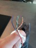
Unfortunately I only see 6 wires (red and black are from the AC source socket) and I have no clue which wire should be where. I have googled for a while now and I only find solutions for grey, yellow, etc. cables. I have the following cable colors showing up:
these are almost complete as the "normal" 8 wires, but I have no idea how to connect them (or if wires need to be combined)
Does anyone of you know how to wire this up? I am thinking of having a piece of CAT5e/6 wire with a connector on it on one side and soldering the wires carefully on the cutted side?
thanks in advance,
Regards
RG
I'm new on this forum, so hopefully I'm posting this thread correctly here. I'm having the following problem after finding out why my HFW2431SP was not operating anymore. Unfortunately the connector (IP - POE) was completely rusted and gone. I had to cut of the original white connector socket. I was hoping to cut of the connector and crimp a new RJ45 connector on it, connector block and done....
Unfortunately I only see 6 wires (red and black are from the AC source socket) and I have no clue which wire should be where. I have googled for a while now and I only find solutions for grey, yellow, etc. cables. I have the following cable colors showing up:
- brown
- blue
- white-green
- green
- white orange
- orange
these are almost complete as the "normal" 8 wires, but I have no idea how to connect them (or if wires need to be combined)
Does anyone of you know how to wire this up? I am thinking of having a piece of CAT5e/6 wire with a connector on it on one side and soldering the wires carefully on the cutted side?
thanks in advance,
Regards
RG