Ubiquiti Lite AP AC (LAP-120-US) connecting to Nanostations (NS-5AC-US)

Henry P

n3wb
Joined
Jun 17, 2024
Messages
5
Reaction score
0
Location
Dallas
Hello,

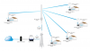
I am currently taking on a project to put cameras on light poles surrounding our property. I have ordered 6 of the LAP’s (building is massive and that many is required to have line of sight to the nanostations) and I’ve got 10 nanostations (1 for each pole). I’ve been able to log into to both and do the initial setup but I haven’t gotten the settings right. They aren’t connecting. I got it to connect once and the camera did display but a tech support guy said I had them wrong and that they needed to be changed. I changed them and now they don’t connect. Can anyone help with this please.

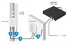
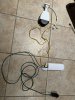
Also, what does someone have a wiring diagram of how it’s all supposed to be connected on the pole side. I have a nano station, it’s power adapter, the Ethernet surge protector, and I’ve ordered a 24v to 48v converter to add after the nanostation to power the camera.

Thanks in advance for the help!
 

TonyR

IPCT Contributor
Joined
Jul 15, 2014
Messages
17,577
Reaction score
40,912
Location
Alabama
Issue #1: Did you follow this guide? => airMAX - Guide to Configure a Point-to-Multipoint (PtMP) ISP-Style Access Point
Note the differences in settings for "AC" devices (as you have) in left column and for "M" devices in the right column.

Issue #2. According to the specs, the NS-5AC can use 802.3af/at POE like the camera so there is no need to convert it to passive 24VDC or furnish 24VDC to the Ubiquiti and try to convert it to 48VDC for the camera. In addition, and I may be wrong here, but I've read somewhere that what goes in on the primary Ethernet port goes out on the secondary port so that a POE camera can be connected there.
 
Last edited:

TonyR

IPCT Contributor
Joined
Jul 15, 2014
Messages
17,577
Reaction score
40,912
Location
Alabama
Ubiquiti ETH-SP-G2 surge protector:

ubiquiti_ETH-SP-G2_surge.jpg

EDIT 6/18 @ 0741 CDT: I cannot locate it now in writing but did read it many years ago but pretty sure it still applies: Ubiquiti requires shielded (STP) cable on all outdoor AirMax installs. My impression at the time was that it is a condition of their warranty as well. I used their outdoor-rated CAT-5e cable ("ToughCable Pro") that was shielded and their metal RJ-45's ("ToughCable Connectors") with a crimp-eyelet for the shield drain wire.
 
Last edited:

Henry P

n3wb
Joined
Jun 17, 2024
Messages
5
Reaction score
0
Location
Dallas
Issue #1: Did you follow this guide? => airMAX - Guide to Configure a Point-to-Multipoint (PtMP) ISP-Style Access Point
Note the differences in settings for "AC" devices (as you have) in left column and for "M" devices in the right column.

Issue #2. According to the specs, the NS-5AC can use 802.3af/at POE like the camera so there is no need to convert it to passive 24VDC or furnish 24VDC to the Ubiquiti and try to convert it to 48VDC for the camera. In addition, and I may be wrong here, but I've read somewhere that what goes in on the primary Ethernet port goes out on the secondary port so that a POE camera can be connected there.
Good Afternoon Tony,

Thank you so much for responding to me! I had a quick question for you. The link that you sent has this diagram on it. The only difference for me is that I don't have one main antenna feeding different radios. I have multiple AC's (6 to be exact) feeding 10 radios. So the question I have is, would I set the static IP's for each AC with a +1 increment, and then continue that trend onto the nanostations as well? So for example:

AC 1: 192.168.1.2
AC 2: 192.168.1.3
AC 3: 192.168.1.4
AC 4: 192.168.1.5
AC 5: 192.168.1.6
AC 6: 192.168.1.7
Nano 1: 192.168.1.8
Nano 2: 192.168.1.9
Nano 3: 192.168.1.10
Nano 4: 192.168.1.11
Nano 5: 192.168.1.12
Nano 6: 192.168.1.13
Nano 7: 192.168.1.14
Nano 8: 192.168.1.15
Nano 9: 192.168.1.16
Nano 10: 192.168.1.17
 

Attachments

TonyR

IPCT Contributor
Joined
Jul 15, 2014
Messages
17,577
Reaction score
40,912
Location
Alabama
That would likely work but the 6 AC's (Access Points) should have different SSID's (wireless signal names) and the 10 radios should be connected individually to a specific AP that provides the strongest signal to that radio.

The 6 AC's should also be set to different 5 GHz channels to help mitigate interference with each other.
 

Henry P

n3wb
Joined
Jun 17, 2024
Messages
5
Reaction score
0
Location
Dallas
So I logged into them and changed the settings as stated above with the different static IP’s. And I’ve only done one AC and one nano. And they aren’t connecting to each other. I’ve put in specific ssid names for them so I know which one is which. But when plugging up the nano, it doesn’t connect to the AC. (Picture shows the lights I’m seeing once it’s been power cycled and running)

Also attached is a picture of how I’m laying it out on the nano side. I have the surge protector but it’s not shown as I’m just trying to get things going but am doing this right? Also, I’m using a different 48v power adapter so that’ll be different. The one I’m using now is an ipcampower one.
 

Attachments

Teken

Known around here
Joined
Aug 11, 2020
Messages
1,757
Reaction score
3,137
Location
Canada
I haven’t read anything where you indicated there is a Nano Station configured and connected to the internal networks router?!?
 

Henry P

n3wb
Joined
Jun 17, 2024
Messages
5
Reaction score
0
Location
Dallas
I haven’t read anything where you indicated there is a Nano Station configured and connected to the internal networks router?!?
So I’ll be completely honest and say I’m a completely new to all of this. I just assumed that I could plug in these devices into a switch I’m using for my camera system and log into them, change the settings as shown in the above link, and it’ll just start working as intended. When it comes to setting up any type of network stuff, it’s really above my head. I even had to watch several YouTube videos and read several posts just to do that. But in order to save money, I’m taking this project on myself. Things are too expensive and business has been too slow to afford the help.

With that being said, my current setup is: from modem it goes into a microtik system for guest WiFi services and then splits off into a Ubiquiti switch. From there it goes to other Ubiquiti switches that power up indoor AC’s for guest connectivity.. separately coming off of the the main Ubiquiti switch that comes off the microtik, I have another set of switches that powers up my camera systems. I currently have 3 separate systems. (Changing that to two now and eventually just 1). This is all spread over 4 buildings that span across 4 acres. So it’s a big place.

So that’s the run down lol. Any advice for this novice that will get things started for me?
 

Teken

Known around here
Joined
Aug 11, 2020
Messages
1,757
Reaction score
3,137
Location
Canada
Let’s keep this simple and will assume you have configured the Nano Station as outlined in the manual offered by Tony R.

If not, do so now . . .

At this point its important to call out some basic fundamentals as to what this hardware will do vs won't. The NS-5AC-US is intended to connect (bridge) two points together over wireless communications.

This device will not provide any so called (WiFi).

If all you did was connect the (Station) to your router / switch it would obtain a DHCP IP Address. On the other side once the other NS-5AC-US (Access Point) was powered up, and pointed at the (Station) there would be a wireless (bridge) connecting the two together.

You'll know if there is connectivity because the signal (strength) bars will light up indicating the same.

If the pass through port is enabled it will power any POE AF (48 VDC) device connected to it. That could be a wireless (AP) Access Point to provide (WiFi) to anything in its range. Often times a POE pass through switch is connected to the secondary port to support more hardware such as: Camera, Access Point, Sensors, etc.

Setup and build this mini network on the floor . . .

You only need three items which are the two NS-5AC-US pointed at each other and a camera. Connect the camera to the Access Point's pass through POE port. You should be able to see the video feed simply by going to the camera's internal web page.

If you have already setup VLC to view the camera's even better . . .
 

Teken

Known around here
Joined
Aug 11, 2020
Messages
1,757
Reaction score
3,137
Location
Canada
If you haven't seen this video please take a few moments to see how the hardware is setup:


Henry P

n3wb
Joined
Jun 17, 2024
Messages
5
Reaction score
0
Location
Dallas
If you haven't seen this video please take a few moments to see how the hardware is setup:

So I watched the video and there are a few key differences in this video to my setup.
1) He's doing a nano to nano connection whereas mine is LAP to nano
2) He's video is from 6 years ago, and the options that he has under his settings are different than mine.
3) Even after trying the different settings, just to get these two to connect, I still haven't had any luck getting the two devices to speak to each other. The nano, when plugged in the way its supposed to be, the signal lights will fully light up for a second then drop, and it'll keep repeating that.
 

Teken

Known around here
Joined
Aug 11, 2020
Messages
1,757
Reaction score
3,137
Location
Canada
So I watched the video and there are a few key differences in this video to my setup.
1) He's doing a nano to nano connection whereas mine is LAP to nano
2) He's video is from 6 years ago, and the options that he has under his settings are different than mine.
3) Even after trying the different settings, just to get these two to connect, I still haven't had any luck getting the two devices to speak to each other. The nano, when plugged in the way its supposed to be, the signal lights will fully light up for a second then drop, and it'll keep repeating that.
I want you to completely forget the device you call a LAP. The LAP is a WiFi Access Point that provides WiFi to other wireless devices.

You need at least two NS-5AC-US devices configured to talk (communicate) to each other.

This is your only goal right now . . .

Define one unit as a Access Point PtP. The other will be defined as Station PtP.
 
Top