Blueprint or your help

Silat_Krav

n3wb
Feb 1, 2025
3
0
France, Fayence (83440)
Hi Guys,
I'm not very familiar with this kind of forum, so in first apology if I not use the right codes.

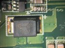
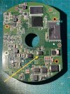
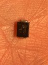
Ok I've got a HIK DS-2CD2155FWD-I a component is dead, a capacitor if I'm right. A friend can swap it but he need to know the "capacity" or tech. spec of this one and isn't readable on it.
So do you have the cam "blueprint" with this kind of detail or someone who have the same cam can take a picture of the component that I'm looking for ?
Please have a look on attached pictures.

Thank you in advance for your time & support.
Regards, Thomas.
 

Attachments

  • HIK_01.jpg
    HIK_01.jpg
    205.5 KB · Views: 0
  • HIK_02.jpg
    HIK_02.jpg
    380.8 KB · Views: 0
  • HIK_03.jpg
    HIK_03.jpg
    181.2 KB · Views: 0
So I am not 100% sure and seeing I am not there to test the area where it was connected here is some info.. If it is for sure a TVS then it would normally be connected between VCC and ground, This would protect against voltage spikes. It can be kind of hard to test these as they can behave like open circuit unless the voltage exceeds the breakdown voltage..
So if it is a Rectifier Diode it would be placed in series with the Power Rail, it would allow the current to flow in 1 direction. In diode mode testing it should conduct in 1 direction and block in the other.
 
  • Like
Reactions: Silat_Krav
So I am not 100% sure and seeing I am not there to test the area where it was connected here is some info.. If it is for sure a TVS then it would normally be connected between VCC and ground, This would protect against voltage spikes. It can be kind of hard to test these as they can behave like open circuit unless the voltage exceeds the breakdown voltage..
So if it is a Rectifier Diode it would be placed in series with the Power Rail, it would allow the current to flow in 1 direction. In diode mode testing it should conduct in 1 direction and block in the other.
Following my understanding, it should be something like that, but I don't need to identify what is this component or what is used for, but what is his value / valor ? Tech specifications to swap it. Am I more "clear" ? Sorry my english isn't fluent and this topic is VERY specific
 
Well to be honest there are a lot of things that can be going on with what you have there..

So if I was in charge of repairing this camera, I would have removed the bad part and I would have powered the camera up without it. 1 to see if the camera comes to life without it. Seeing what it should be used for it can work without it.. 2 I would test the defective area to know what I am looking for as a replacement.. If the area was tested and returns that it was 12v then I would replace with SMBJ12A or a P6KE12A, However if it was 24v then I would replace with SMBJ24A or P6KE24A..

However if the camera was to malfunction then it might be a Schottky or Rectifier Diode and would require further testing..

While testing with it powered on without the part installed, I would if I don't know what side is Ground or + I would just use a common Ground like Capacitor Ground side, or shield and or known ground pad as there are many most times on the PCB and testing the voltage on either side of the 2 pads the part was removed from.

Keep in mind that I personally doubt it is a Schottky seeing there is already one there that is rated for 40v and 3amps. That is the DC blocking voltage and average forward current of the SK34 that it was inline with.. Again it is hard to know what the part is as there is no data sheet for the part and could be of many different uses.. Again testing it would be really only way to know what is best to replace it with..
 
  • Like
Reactions: Silat_Krav
Well to be honest there are a lot of things that can be going on with what you have there..

So if I was in charge of repairing this camera, I would have removed the bad part and I would have powered the camera up without it. 1 to see if the camera comes to life without it. Seeing what it should be used for it can work without it.. 2 I would test the defective area to know what I am looking for as a replacement.. If the area was tested and returns that it was 12v then I would replace with SMBJ12A or a P6KE12A, However if it was 24v then I would replace with SMBJ24A or P6KE24A..

However if the camera was to malfunction then it might be a Schottky or Rectifier Diode and would require further testing..

While testing with it powered on without the part installed, I would if I don't know what side is Ground or + I would just use a common Ground like Capacitor Ground side, or shield and or known ground pad as there are many most times on the PCB and testing the voltage on either side of the 2 pads the part was removed from.

Keep in mind that I personally doubt it is a Schottky seeing there is already one there that is rated for 40v and 3amps. That is the DC blocking voltage and average forward current of the SK34 that it was inline with.. Again it is hard to know what the part is as there is no data sheet for the part and could be of many different uses.. Again testing it would be really only way to know what is best to replace it with..
Thx for your time and advices I will share this with my friend and be back to you asap.