Hi there, I have this IP camera, from the brand of Shenzhen Xuanyuanxing Electronic Technology Co., Ltd. (good luck trying to say that) and i've been using one of their cameras (IT Camera X5 (2A2NI-X5)), I don't have any issues, but i've been trying to see if I don't have to use their proprietary software, so I opened up the camera and there's not really much to work off except for the SoC chip labelled Augentix HC1703, I've googled and researched this chip but it seems like the only people who have ever talked about it are the company, people selling the boards, and this Russian forum who mention it: the forum in question so, not much to work off. I did find the patents for the camera itself from the fcc but again, not much to work off. So i'm stuck, i've looked into similar (i think) chips which mentioned to use serial which can get you into the linux shell (which I can confirm this camera does have, it had an update which included uboot). I have scanned the ip behind the camera but the ports that are open do confuse me, theres no web ports or telnet ports, but random ones: 1214/udp 4500/udp 6050/udp 17505/udp 18255/udp 21364/udp 21644/udp 21847/udp 21868/udp 36206/udp 38498/udp 42639/udp, I do hope someone can help me figure out if this camera is even possible to break into and use without it's own app.
Does anyone have any experience with the Augentix HC1703 chip?
- Thread starter GYKGAMER
- Start date
You are using an out of date browser. It may not display this or other websites correctly.
You should upgrade or use an alternative browser.
You should upgrade or use an alternative browser.
Hi GYKGAMER, I played a little bit with a PTZ camera based on the Augentix HC1703 and I can confirm I gained the root on the serial too. My SOC try to run a debug scripts in the boot process and if you create a file debug_cmd.sh on an SD card and you will be maybe able to execute bash commands from it. Note my SD card is mounted in /mnt and my camera looks for /mnt/debug_cmd.sh similary to the Goke GK7102.
Last edited:
On the Augentix HC1703L check GitHub - Jalecom/AJ_HC1703L_Teardown: PTZ IPCam based on SOC Augentix HC1703L teardown
On the Goke GK7102 check GitHub - ant-thomas/zsgx1hacks: Hacks for ZS-GX1 IP Camera and various Goke GK7102 based IP Cameras
On the Goke GK7102 check GitHub - ant-thomas/zsgx1hacks: Hacks for ZS-GX1 IP Camera and various Goke GK7102 based IP Cameras
You say you got root access through serial, but do you need to do that to use your github repo? I'm just asking because I don't have any experience with serial at all, I only mentioned it because other ip cameras need it.Hi GYKGAMER, I played a little bit with a PTZ camera with the Augentix HC1703 and I can confirm I gained the root on the serial too. My SOC try to run a debug scripts in the boot process and if you create a file debug_cmd.sh on an SD card and you will be maybe able to execute bash commands from it. Note my SD card is mounted in /mnt and my camera looks for /mnt/debug_cmd.sh exactly as the Goke GK7102.
No, If you find the two serial pin (pay attention 3,3V, you need an adapter) you can stop the boot process in several different ways. You can even stop the autoboot of UBoot by hitting a key, so very early. In this case you're in, phisically attached to the SoC as root.
However, if your camera looks for the debug_cmd.sh on the SD, you can execute any command you write in the file with roots privilege.
However, if your camera looks for the debug_cmd.sh on the SD, you can execute any command you write in the file with roots privilege.
On my AJ HC1703L it is possible to load from SD a SSH Server and start it with few commands on the debug_cmd.sh, then any command is executed as root
The camera's behaviour appears very similar to the Goke GK7102 Cloud IP Cameras, and many of the hack are effective on my camera as well. I can pan and tilt the camera, switch on the white LEDs and the IR LEDs too
The camera's behaviour appears very similar to the Goke GK7102 Cloud IP Cameras, and many of the hack are effective on my camera as well. I can pan and tilt the camera, switch on the white LEDs and the IR LEDs too
My camera doesn't have any 3.3v labelling? To be fair it isn't a PTZ camera, mines like a smaller form factor one,No, If you find the two serial pin (pay attention 3,3V, you need an adapter) you can stop the boot process in several different ways. You can even stop the autoboot of UBoot by hitting a key, so very early. In this case you're in, phisically attached to the SoC as root.
However, if your camera looks for the debug_cmd.sh on the SD, you can execute any command you write in the file with roots privilege.
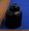 and I have tried to use the debug_cmd.sh onto my sd card but nothing changes, I think my camera doesn't check that file, I don't think my camera even accepts serial? Unless you can point them out in the internals of the camera
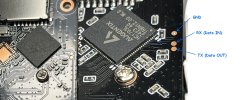
It seems no serial pad are visible near your Augentix SoC however you can look for a 57'600bps signal on the SoC pins: the processor usually send out a lot of information while it boot and run. I found my two UART pad near the SoC and the copper tracks are visible on my PCB until the HC1703L pins; see the picture here below: probably you have the serial on the same pins. Remember to use a 3.3V serial converter (i.e. FTDI chip or equivalent) or you will burn the SoC with a 5V or 12V standard serial

Last edited:
I had a real good look at my SoC, and unless I'm missing something, they either lead to nowhere or to the stuff that power it / what it controls, I don't see anything which could be of use (see image below of a close up), I don't really have any other ideas other than to desolder the chip and read it, but I will say this right now, not doing that.
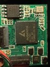

No, desolder the Soc is not an option. I suggest to check the pins next the "H" of the HC1703 SoC: as in my camera the serial in/out are there, I hope you will have the same configuration of GPIOs
Use an oscilloscope or a logic analyzer (less than 10€ on ebay) to check if a 57'600bps or 115200bps output is present. In that case you can connect a 3.3V serial adapter and you will see the log of the boot, some similar to my boot serial log
Good luck!
Use an oscilloscope or a logic analyzer (less than 10€ on ebay) to check if a 57'600bps or 115200bps output is present. In that case you can connect a 3.3V serial adapter and you will see the log of the boot, some similar to my boot serial log
Good luck!
Never used a raspberry, however if it has a high impedence 3.3V serial input, you can use it too. Configure the terminal settings to 115200 bps baudrate, 8 bits, no parity, 1 stopbit, no flow control. If you get garbage try to slow down to 57600 bps
The TX of the SoC is easy to find because you get redable data out
Don't connect the RX unless you found the correct one or you will fry the port
Read the step 3 and 4 of wiki/en/installation.md at master · OpenIPC/wiki for a quick overview of UART to camera connection
The TX of the SoC is easy to find because you get redable data out
Don't connect the RX unless you found the correct one or you will fry the port
Read the step 3 and 4 of wiki/en/installation.md at master · OpenIPC/wiki for a quick overview of UART to camera connection
Last edited:
Hi there, sorry for no response for a long time, I currently have exams going on and there's still a week left of them. I haven't had time to work on the camera but I did want to do a quick check up. I did a little digging and found this diagram of the camera, there's no pinout but it shows something. (First Image) I see UART at the bottom middle of it so looking at the image of the camera I do see something which could be TX/RX (Second image) However there's only 2 pads and there's no ground pad which looking at your github link. Though I think I can achieve that with just adding a wire to the micro sd card shell. What are your opinions on this? I'm just not really good at all with electronics but do want to develop my knowledge at some point.
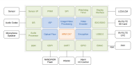


Here's where I found that image of the pinout by the way: Augentix - Low Power SoC Edge Security Solution ->
Hi Gikgamer,
Unfortunately the two holes you marked are connected eachother, I suppose the signal will go on the other side of the PCB. I don't see any pad there and I would check the same pin of the SoC where I have the serial data out: you can attach a wire to the SD card shell, or to the pin 4 of the XMC integrated circuit wich usually is the GND, or to one of the connectors you have on the PCB; then I would try to find a data out from the SoC with the RX of your raspberry. See marks on the image here below:
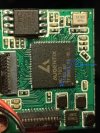
Unfortunately the two holes you marked are connected eachother, I suppose the signal will go on the other side of the PCB. I don't see any pad there and I would check the same pin of the SoC where I have the serial data out: you can attach a wire to the SD card shell, or to the pin 4 of the XMC integrated circuit wich usually is the GND, or to one of the connectors you have on the PCB; then I would try to find a data out from the SoC with the RX of your raspberry. See marks on the image here below:

Wow, nice! Uploaded on the repository. Thank you.Here's where I found that image of the pinout by the way: Augentix - Low Power SoC Edge Security Solution ->
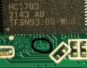
Sorry again for the late reply, The issue i'm having is the fact that the pins on the SoC are absolutely tiny, I mean a grain of rice is probably bigger then the pins, it looks larger because I just zoomed in. I don't think it would be possible for me to solder that. What could I do really now?
Not so much: if you have no pad (bigger than the tiny pin) and you can't find any different place to solder a single tiny wire, or to use a needle tip to look for the serial out... You will have no chance to get the data out.Sorry again for the late reply, The issue i'm having is the fact that the pins on the SoC are absolutely tiny, I mean a grain of rice is probably bigger then the pins, it looks larger because I just zoomed in. I don't think it would be possible for me to solder that. What could I do really now?
I used the custome firmware from a micro SD Card from

 github.com
Mine is a HC_1703 but this did work to get me browser based PTZ controls, FTP and SSH.
I think it still talks to China and the camera is still viewable in the app, but it is a start
GitHub - Jalecom/AJ_HC1703L_Teardown: PTZ IPCam based on SOC Augentix HC1703L teardown
PTZ IPCam based on SOC Augentix HC1703L teardown. Contribute to Jalecom/AJ_HC1703L_Teardown development by creating an account on GitHub.
I think it still talks to China and the camera is still viewable in the app, but it is a start
