
Just wanted to clarify how the I/O terminal at the back of the camera works with a simple painting.
I have been in contact with hikvision about how to connect things to the alarm I/O terminal a loooong time
but not received any answer at all so I picked it apart which was simple.

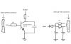
The output is open collector type and has no overvoltage/dump protection but relais on this 75ohm resistor which is good to keep in mind if connecting directly to a relay etc.. It uses a little NPN sot23 transistor to switch load.
To utilize this output you need to connect your load between +12V camera supply and the output terminal.
The output will handle up to 40V so switching for example 24V relays are possible.
The input reacts to an active low signal referenced to cameras system ground.
The input is in series with a small diode which in turn is in series with 2 parallell 10k resistors.
The input has no apparent overvoltage structure but relies solely on the resistors and the internal railclamps
on the ambarella chipset or whatever ic it goes to.
It would be interesting to know how the other cameras I/Os looks like
how does the 2532 or 2732 look like - are they the same
or do they use an optocoupler solution instead.
How does the 1-pin audio interface work?.
I have been in contact with hikvision about how to connect things to the alarm I/O terminal a loooong time
but not received any answer at all so I picked it apart which was simple.
The output is open collector type and has no overvoltage/dump protection but relais on this 75ohm resistor which is good to keep in mind if connecting directly to a relay etc.. It uses a little NPN sot23 transistor to switch load.
To utilize this output you need to connect your load between +12V camera supply and the output terminal.
The output will handle up to 40V so switching for example 24V relays are possible.
The input reacts to an active low signal referenced to cameras system ground.
The input is in series with a small diode which in turn is in series with 2 parallell 10k resistors.
The input has no apparent overvoltage structure but relies solely on the resistors and the internal railclamps
on the ambarella chipset or whatever ic it goes to.
It would be interesting to know how the other cameras I/Os looks like
how does the 2532 or 2732 look like - are they the same
or do they use an optocoupler solution instead.
How does the 1-pin audio interface work?.
Attachments
-
 18.1 KB Views: 135