okestone
n3wb
I need a Ethernet/power cable pigtail for an EmpireTech 4MP Ultra Low Light Turret IP Camera. Is there anywhere to buy one? I'm not having any luck.

It should come with a pigtail for both Ethernet and separate power. But is there a reason you aren't just connecting it with PoE (Power over Ethernet) so you don't need a separate power connection at the camera?I need a Ethernet/power cable pigtail for an EmpireTech 4MP Ultra Low Light Turret IP Camera. Is there anywhere to buy one? I'm not having any luck.
") This camera was installed and working for a couple of years until moisture got in the RJ45 part of the pigtail connector and corroded it. I have tried everything to clean it up and resurrect it, but to no avail. So I need to replace it if possible.
This camera was installed and working for a couple of years until moisture got in the RJ45 part of the pigtail connector and corroded it. I have tried everything to clean it up and resurrect it, but to no avail. So I need to replace it if possible.
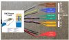
Sure! Standard RJ45 pin-out, except red goes to pin#5 (blue stripe) and black to pin #7 (brown stripe).That's great new!
Care to share which color goes to which pin of the RJ-45 so as to maybe help someone else?
As a fly on the wall, I'm thinking it was a mistake to hook the red and black wires to the rj45. The red and black wires are for the 12 volt power input. If you connect to a POE switch (usually running POE mode A) it might be moot. But if you use a POE injector (usually mode B) you'll be sending nominal 48 volts into the camera's 12 volt input. It's possible that with the intact pigtail, the brown wire goes to both pins 7 and 8 of the RJ45, and the blue wire to pins 4 and 5.Standard RJ45 pin-out, except red goes to pin#5 (blue stripe) and black to pin #7 (brown stripe).
That's correct. ...thus leaving 2 pins for the red and black power supply. Any way, it works great.I think only 6 wires are crimped into the RJ-45 on Dahua OEM's
You might as well be talking to yourself, IMO....my suggestion for using a DVM or continuity checker to confirm wire color to pin assignment was apparently ignored as well, so.....As a fly on the wall, I'm thinking it was a mistake to hook the red and black wires to the rj45. The red and black wires are for the 12 volt power input. If you connect to a POE switch (usually running POE mode A) it might be moot. But if you use a POE injector (usually mode B) you'll be sending nominal 48 volts into the camera's 12 volt input. It's possible that with the intact pigtail, the brown wire goes to both pins 7 and 8 of the RJ45, and the blue wire to pins 4 and 5.
Here's a picture somebody else made for an older camera. No guarantee that the red/black situation is the same for yours, but I'd be willing to bet a nickle that it is.
View attachment 187769