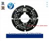
My thoughts here looking the first picture of the board:
The requested signal will be necessary to command the IR filer mecanically if front of the video chip.
So somewhere you need some signal with enough power for the command, thing the captor itself cannot provide.
I'm not quite confident to connect to one pin of the D/N captor, as in most of cases this is a variable resistance, so the value cannot be 0 or 1. So for me not logic command at all.
So I will go more to the transistor itself you have near the IR sensor who probably will generate the trigger signal. For that, you will need a voltmeter and check day/night and observe the results.
transistor is the one right to the R1 resistor/ 3 pins.
So take care not to destroy it generating a short circuit.
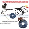
Other issue can be the trigger itself is not Embedded on this board, but in another one, so in this case you need to solder directly to the senson (one side or the other/ you need to try which one is OK), the the variable value depending of the light will trigger in another board the Day/Night component driver for the mecanical IR filter.
Here, as just power on by 12v the board, all necessary is Embedded, including the drivers to light le leds.
But again, Look around the transistor, I think this is the issue.
When it works correctly, you hear the IR filter switching from day to night.
This is the only logic way to proceed, when you don't have any schematics provided with the board.
The best is to use an oscilloscope, to see exactly the switching points, etc...
Some additional info, with some cams, where the day/night sensor sensitivity is not improved, you have always a fixed resistor in serial with the light sensor on the pcb board.
So some times, to finetune the switching due to very poor sensitivity and quality of the sensor (too much or not enough), you need to replace fixed value of this resistor by a variable resistor to adapt to your environnement and finetune the hardware settings. This happens very often when you play with DIY components and made your assembly yourself
Doesn't happens with manufactured cams as the balance and settings where made from engineering build, but can happens when you replace the original IR and captor board with a similar one, who looks the same but from another manufacturer who mades their own cooking .
Hope this helps .