[FONT="]Hello,[/FONT]
[FONT="]I've got a new IP camera and and am just trying to figure out the PIN outs to connect the wires. [/FONT]
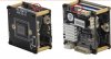
[FONT="]On the power outlet there are 4 pins, 12v CMT_R tap, CMT_T tap and G. [/FONT]
[FONT="]I've never seen the CMT_R/CMT_T pins before and am not sure what they are. I've googled a bunch and can't find an explanation. Maybe these are RX/TX pins?[/FONT]
[FONT="]Does anyone know? The cam pin out / cam can be seen here :[/FONT]
[FONT="]http://imgur.com/a/OMNeM[/FONT]
[FONT="]Thanks![/FONT]
[FONT="]Mike[/FONT]
[FONT="]I've got a new IP camera and and am just trying to figure out the PIN outs to connect the wires. [/FONT]
[FONT="]On the power outlet there are 4 pins, 12v CMT_R tap, CMT_T tap and G. [/FONT]
[FONT="]I've never seen the CMT_R/CMT_T pins before and am not sure what they are. I've googled a bunch and can't find an explanation. Maybe these are RX/TX pins?[/FONT]
[FONT="]Does anyone know? The cam pin out / cam can be seen here :[/FONT]
[FONT="]http://imgur.com/a/OMNeM[/FONT]
[FONT="]Thanks![/FONT]
[FONT="]Mike[/FONT]