SV3C Wiring pin out

LeeBuck

n3wb
Joined
Oct 2, 2016
Messages
1
Reaction score
0
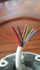
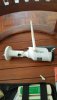
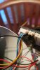
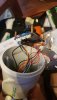
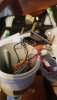
Hello everyone, I need some help figuring out the wiring on an SV3C B01-1080P-POE camera. I was wondering if anyone knew the pin out on the wires to add a new male or female RJ-45 with POE to the camera. I unfortunately no longer have the factory female end that was on it to test the pin out myself. The wires on the camera are:

Orange
Orange/White
Green
Green/White
Blue
Red
Black

If anyone has any idea I would greatly appreciate the help!

Thanks!
 
Joined
May 6, 2017
Messages
3
Reaction score
3
A little late but maybe it will help someone else.....

To put a male end on with cat5 cable:

Orange to blue
Orange/White to blue white
Green to green
Green/White to green white
Blue to yellow
Red to unused
Black to unused
Brown white and brown to grey
 

N00b_2020

n3wb
Joined
Dec 4, 2019
Messages
8
Reaction score
1
Location
London
Hi, sorry to reach out to an old post. I had this setup in my house which the builder frustratingly had cut the cable. I'm able to crimp rj45's but I just need some clarification.

If I add an rj45 male connector to the snipped part. Does this comply with t658b standards? I was confused with the above post

"
Orange to blue
Orange/White to blue white.."

Is someone able to break this down for me exactly would really appreciate it.

Thanks!
 

TonyR

IPCT Contributor
Joined
Jul 15, 2014
Messages
16,433
Reaction score
38,153
Location
Alabama
Hi, sorry to reach out to an old post. I had this setup in my house which the builder frustratingly had cut the cable. I'm able to crimp rj45's but I just need some clarification.

If I add an rj45 male connector to the snipped part. Does this comply with t658b standards? I was confused with the above post

"
Orange to blue
Orange/White to blue white.."

Is someone able to break this down for me exactly would really appreciate it.

Thanks!
No, the OP was trying to replace a pigtail from a cam which has it's own color code and they can vary among manufacturers and models.

If you are putting a RJ-45 on one end of CAT-5e or 6 that has an RJ-45 on the other end, then replicate what's on the OTHER end, A or B. Although Auto MDI-X allowed for using one of each on either end (A on 1, B on the other) since the late 90's, it's best to keep both ends the same so a simple, manual tester gives the expected results.
Additionally, in North America the predominant standard is T-568
B.

If installing from scratch or terminating both ends, then use the T-568B standard on BOTH ends as follows:

RJ45-Pinout-T568B_med.jpg
 
Last edited:

N00b_2020

n3wb
Joined
Dec 4, 2019
Messages
8
Reaction score
1
Location
London
Hi Tony, thank you for your speedy repsonse!

Their appears to be some confusion.

It's the cable attached the the camera which had the female connecter, reset button and power which had been cut. I can now only see the cables coming out from the camera.

The idea was to crimp the camera itself with male rj45 connector and effectively using it on a connector as poe only (bypassing the power and reset switch) but was wondering if the colour coding was still the same for a t568b standard. I'm aware that the colour coding varies from camera models. Had that issue with a China made camera which had its own standard and was painful to identify.

Thanks!
 

TonyR

IPCT Contributor
Joined
Jul 15, 2014
Messages
16,433
Reaction score
38,153
Location
Alabama
It's the cable attached the the camera which had the female connecter, reset button and power which had been cut. I can now only see the cables coming out from the camera.

The idea was to crimp the camera itself with male rj45 connector and effectively using it on a connector as poe only (bypassing the power and reset switch) but was wondering if the colour coding was still the same for a t568b standard. I'm aware that the colour coding varies from camera models.
Do you still have the pigtail that the "builder" cut?

If not, then a make and model of camera may help, along with a list of the current wire colors on what's left of the pigtail.
 

N00b_2020

n3wb
Joined
Dec 4, 2019
Messages
8
Reaction score
1
Location
London
Hi!

I don't have the pigtail unfortunately as they also through it out!

Current cable colours look similar to rj45 with an additional red and black cable presumably for power. The builders did a clean cut so I'll need to strip them a bit to see what exactly they are when I get home. I'll attach a photo asap.

Model SV3C B01 960p
 

TonyR

IPCT Contributor
Joined
Jul 15, 2014
Messages
16,433
Reaction score
38,153
Location
Alabama
Hi!

I don't have the pigtail unfortunately as they also through it out!

Current cable colours look similar to rj45 with an additional red and black cable presumably for power. The builders did a clean cut so I'll need to strip them a bit to see what exactly they are when I get home. I'll attach a photo asap.

Model SV3C B01 960p
I think what @Fairbarnacle was stating is that the left is the RJ-45 and the right is the pigtail...is that correct, @Fairbarnacle ?
To clarify, below is a left to right match with pin numbers of an RJ-45 when wired to T-568B standard:

RJ-45 Male---------------------------------Pigtail​
Pin) color​
================================​
2) Orange ---------------------------------blue​
1) Orange/White------------------------blue white​
6) Green-----------------------------------green​
3) Green/White ------------------------green white​
4) Blue--------------------------------------yellow​
7) & 8) Brown/white & brown------grey​
=================================​
 

N00b_2020

n3wb
Joined
Dec 4, 2019
Messages
8
Reaction score
1
Location
London
Thanks very much Tony!

Apologies for the lateness. I've managed to get back and strip the cables. Please see attached images.

There appears to be a mix of standard and non standard colour coding for cables coming out the camera.

Standard
White Blue
Blue
White Green
Green

Non standard
Yellow
Dark Blue
Grey
Fat Black
Thin Black
Fat Red
Thin Red

I presumably like to think the red and black cables are for power/poe maybe?

Would you be able to break this down a little bit more for a noob like me? (I'm sorry) just trying to get to grips with this.

Looking at the image you kindly provided me for a t-568b

Screenshot_20191207-073058_CM Browser.jpg

While looking at the male connecter (clip side down as per the image) I'm just trying to figure out where they go exactly as per the cables I have.

A few notes on this the "Fat black" & "Fat Red" will not fit in the male rj45 connector as the cable is obviously thicker than the others. If those are for power, I'm more than happy to create a dc cable plug for them as it was originally as per the image I have attached Re the power pigtail connector.

Thanks v much again for your help!
 

Attachments

TonyR

IPCT Contributor
Joined
Jul 15, 2014
Messages
16,433
Reaction score
38,153
Location
Alabama
There's also a purple in there that's not on your list or @Fairbarnacle 's ! Jeez, I dunno, man. Wish I could offer better ideas.

About the only thing I could say is that possibly the thick red and thick black is for 12VDC power, positive and negative respectively and the thin red and thin black is the reset button ...note that I said "possibly".

The camera is not POE .

That is a low-res camera, under $50. I think I'd toss it and buy another camera and not waste another minute of my time...and not let that "builder" near my house again, at least if it involves anything electronic , electrical or wiring...PERIOD. :(
 

N00b_2020

n3wb
Joined
Dec 4, 2019
Messages
8
Reaction score
1
Location
London
Hey man! That's no problem at all. Thank you for your help and replies though. I'll still try see what I can do. These cameras are not easy to come by where I am.
 

fergenheimer

Getting comfortable
Joined
Oct 19, 2018
Messages
320
Reaction score
714
Location
SWTexas
Hello N00b_2020,
I'm sure that I did the same Google search that you did and came up with the same information. Since that is nothing, everything I say is a GUESS and you would risk screwing up your camera if I am wrong. Listen at your cameras peril.
I would hook up 12vdc to the large red (+) and black (-). The small red an black are probably the resets. They are probably normally open and the reset button would be a momentary shunt. I would leave them unattached. The yellow, purple and gray are probably unused since the sparse documentation for that model does not show any alarm contacts. I have seen well known cable manufactures label cables as cat5(e) and only include the inner sets of twisted pairs. It looks like this might be the case. If you are not going to use the pairs, why go to the expense? I would use the green/green-white and blue/blue-white as shown in the pictures above. Do not land any of the other wires into the RJ-45 end. If you were to disassemble the camera and look at the boards, you might get more of an insight. Good look at getting it booted and logged into.
 

N00b_2020

n3wb
Joined
Dec 4, 2019
Messages
8
Reaction score
1
Location
London
Hi Fergenheimer! Thank you!

Ofcourse it's all guessing at the moment and appreciate your help. I've got nothing to lose to be honest and might as well try see what I can do. I'll report in shortly.
 
Joined
May 6, 2017
Messages
3
Reaction score
3
The pinout I posted was for a different SV3C camera that I was using at the time. I used to solder ethernet cable to the camera wires hence the odd pinout description. We are now using the "SV-B06POE-4MP-A" and find the following pinout to work. It is possible to crimp the camera wires in an RJ45 connector.

White Blue, Blue, White Green, Yellow, blank, Green, Grey, blank

Next iteration will be to replace the SV3C cable with an ethernet cable pigtail. I believe they are molex picoblade connectors on the board.


View attachment 51743
 
As an Amazon Associate IPCamTalk earns from qualifying purchases.

N00b_2020

n3wb
Joined
Dec 4, 2019
Messages
8
Reaction score
1
Location
London
Thanks very much for this.

I've just tried to do this and connected to a male rj45:

White Blue,
Blue,
White Green,
Yellow,
blank,
Green,
Grey,
blank

.. Doesn't work unfortunately, found it a bit tricky to get them in with the blanks but I'm. Pretty sure I did it right. However, Fat Red and Fat Black cables were indeed DC as I can see it coming on now after soldering those. I did also open up the unit to see if it helps (attached).

I appreciate there's not much you can help with as you have very much already but thought I'd send this across one last time with the updated images.

Thanks!
 

Attachments

Joined
May 6, 2017
Messages
3
Reaction score
3
Sorry to hear it didn't work. The other engineer here has been working with them lately so I'm just passing along what he told me but we have 6 of them working using this method. I'll try to document it better next time we make one up.
 

vvv1vvv

n3wb
Joined
Jul 9, 2017
Messages
1
Reaction score
0
A little late but maybe it will help someone else.....

To put a male end on with cat5 cable:

Orange to blue
Orange/White to blue white
Green to green
Green/White to green white
Blue to yellow
Red to unused
Black to unused
Brown white and brown to grey
Thank you so much, mine rusted and had to cut them.
 

Froggy85

n3wb
Joined
Jul 9, 2020
Messages
2
Reaction score
2
Location
Mexico
A little late but maybe it will help someone else.....

To put a male end on with cat5 cable:

Orange to blue
Orange/White to blue white
Green to green
Green/White to green white
Blue to yellow
Red to unused
Black to unused
Brown white and brown to grey
Thank you, Fairbarnacle. I used this to connect an RJ45 male connector to the pigtail of the SV3C bullet type camera, SV-B01-1080P-POE. The pigtail was damaged.

The pattern worked for me, but, with the following adjustment: since Grey cannot be connected to both "Brown/W and Brown", I tried Grey on Brown, pin # 8, and it worked.
So, following the T-568B by pin number, you get...
1 - Blue-W
2 - Blue
3 - Green-W
4 - Orange
5 - N/A
6 - Green
7 - N/A
8 - Grey
 
Last edited:

danwhite99

n3wb
Joined
Dec 14, 2014
Messages
15
Reaction score
2
Location
syracuse ny
Thank you, Fairbarnacle. I used this to connect an RJ45 male connector to the pigtail of the SV3C bullet type camera, SV-B01-1080P-POE. The pigtail was damaged.

The pattern worked for me, but, with the following adjustment: since Grey cannot be connected to both "Brown/W and Brown", I tried Grey on Brown, pin # 8, and it worked.
So, following the T-568B by pin number, you get...
1 - Blue-W
2 - Blue
3 - Green-W
4 - Orange
5 - N/A
6 - Green
7 - N/A
8 - Grey
Back in October of 2016 Lee Buck started off with a question about replacing a connector on his camera. I have the same issue
Sv3C SV-801. my wires are as his, but the solution made mention of a yellow wire (blue to yellow) in the cate5e connector. Ii can not fine any referance to a yellow wire or pin.
hope this makes sense.
any help is greatly appreciated.
 
Top