Swann NHD-806 PoE IP Cam Wiring Pin Out (damaged RJ45 camera socket)

Netwalker

Getting the hang of it
Joined
Aug 8, 2017
Messages
46
Reaction score
28
Since we’re digging up posts from 2016, I’ll add that CorrosionX HD seems to work on my RJ-45 connectors (doesn’t cause any transmission/Poe issues), so I plan to put it on all my non environmentally conditioned connections after watching the guys from flight test soak their rc equipment in it.

That way maybe I never have to deal with this.
 
Joined
Jun 29, 2019
Messages
3
Reaction score
0
Location
Houston, TX
Since we’re digging up posts from 2016, I’ll add that CorrosionX HD seems to work on my RJ-45 connectors (doesn’t cause any transmission/Poe issues), so I plan to put it on all my non environmentally conditioned connections after watching the guys from flight test soak their rc equipment in it.

That way maybe I never have to deal with this.
Uhhhh what? Do people actually read what the original question was? And I’m not digging up old posts. This was technically never answered, and thus the question was asked again. Also, I just provided, for the first time ever, mind you, how the wiring for the Swann PoE cameras are soldered in color order after exposing the keystone jack. I haven’t seen anyone provide that yet.
 

nurain

n3wb
Joined
Jul 6, 2020
Messages
1
Reaction score
0
Location
uk
I know this is a super old post but does anyone have any help/advice for the Swann 810 camera? I have a damaged cable and have 12 colours in total.

Thanks in advance
 

Attachments

Adrian83

n3wb
Joined
May 13, 2021
Messages
1
Reaction score
0
Location
New York
OK, poking around with a multimeter set for dc volts ;

Pin 7 to Pin 4 & 5 (common) - 48 V
Pin 8 to Pin 4 & 5 (common) - 48 V

So looks like Mode B PoE. Looking at wikipedia Mode B, T568B color schematic, RX+ is on pin 1, and RX- on pin 2, and as you mention, pin 1 & 2 can't be common.

As its only six wires, and it would be obvious that you could common 4 & 5 and 7 & 8 onto one wire each, and then I noticed that the wires I currently had on 7 & 8 matched the T568B colour scheme for RX+ and RX-, it looks like I had 1 & 2 (purple) and 7 & 8 (orange, white/orange) transposed.

Swapped them over, and all working now.

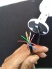
Hence, the correct wiring for this cam is ;

Pin 1 - white wire with orange trace
Pin 2 - orange wire
Pin 3 - Green wire
Pin 4 & 5 common - grey wire
Pin 6 - white wire with green trace
Pin 7 & 8 - common, purple wire

Pic below ;

View attachment 9183

Thanks for the pointers on pins 1 & 2, and that the solder pad number don't necessarily correspond to the RJ45 pin numbers :)
If i rewire with a cat5e connector then pin 4 & 5 along with 7 & 8 can be used without common wiring ? becouse i have 6 wires and 8 connector on the RJ45 (cat6e) connector
 

Attachments

Paul69

n3wb
Joined
Jun 27, 2023
Messages
2
Reaction score
0
Location
california
Has anyone done a solder splice between a NHD-818 CAM and the CAT5 cable. I'd like to eliminate the connectors at the camera end. I have not been able to find the color to color alignment between the 6 wire camera pigtail and 8 wire CAT5 cable.
Any help would be greatly appreciated.

Thanks
Paul
 

Starglow

Getting comfortable
Joined
Dec 13, 2018
Messages
410
Reaction score
695
Location
North Carolina
Has anyone done a solder splice between a NHD-818 CAM and the CAT5 cable. I'd like to eliminate the connectors at the camera end. I have not been able to find the color to color alignment between the 6 wire camera pigtail and 8 wire CAT5 cable.
Any help would be greatly appreciated.

Thanks
Paul
But why...? Soldered connections carry their own set of risks for failure, plus having the added inconvenience of not being able to easily disconnect the cable from the camera.

I'm just trying to understand the logic of eliminating the connector and what benefits you expect to gain by doing so.
 

Paul69

n3wb
Joined
Jun 27, 2023
Messages
2
Reaction score
0
Location
california
But why...? Soldered connections carry their own set of risks for failure, plus having the added inconvenience of not being able to easily disconnect the cable from the camera.

I'm just trying to understand the logic of eliminating the connector and what benefits you expect to gain by doing so.
Connectors have the highest failure rate of numerous electrical connections hence this thread. Soldered connections have a much lower failure rate so I'd rather unsolder to separate the camera if/when needed and live with the high confidence connection.
 
Top