Since the output is latching until you remove power, but does always unlatch when power is interrupted, we know that the outputs of the cameras are not blown (shorted), nor are the contacts of your added relay welding closed.
I think it's safe to say that the relay's coil (your relay) is remaining energized, even if only partially, and only unlatches when you remove power from the system.
Do you have any data on what the cameras use for their alarm outputs? Open collector NPN transistors pulling to ground? An actual relay's dry contacts? A PNP that's meant to "source" current from the high-side? We can't troubleshoot this until we know more about the circuitry in the cameras.
It seems unlikely that they'd use a TRIAC for this alarm output unless they intended you to use an AC device for the alarm.
I'd like to see the specifications for the alarm outputs in the cameras.
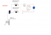
Also, in your schematic, you have a switch drawn in called "Motion Detect". Is this a separate switch you've installed in series with the alarm outputs of the cameras (which are in parallel) so that you can enable and disable the alarm output? If so, can you "unlatch" the alarm by opening that switch, thus removing the current path through the relay's coil?
Regardless, I would ALWAYS install a "bark back diode", reverse biased, across the coil of any relay or inductive load that you're driving with a solid state device (such as a transistor output that we might have in the cameras).
When the switching device in the camera opens (shuts off), the magnetic field around the solenoid of the relay (or other inductive load) will begin to collapse. As the field collapses, the energy stored in that field will need to go somewhere. And what happens is that the voltage across the coil will rise very high if there is no path for that induced current. That high voltage spike can easily damage transistors or other solid state switches, and even cause burning of relay contacts which can immediately (or eventually) lead to contact welding.
I guess we need more information, especially about the circuitry in the cameras' alarm outputs to really understand what's happening. Substituting a solid state relay for the mechanical relay you have now will eliminate the possible inductive spike issues for the cameras' outputs. But if the alarm siren/strobe is running off of DC, you will need a DC output solid state relay. They make them, but they're a bit less common. If what you have ordered is a typical SSR with a TRIAC or back-to-back SCRs for its output, it will actually perform the same latching function you're getting now!
TRIACs and back-to-back SCRs rely on a zero-crossing of the load current to switch off. They are inherently latching devices. Used with an AC load, they switch off as soon as the gate current is removed AND the load current passes through zero. If the load current doesn't go to zero, then they remain switched on (latched on).
If your alarm siren is a DC device, you can't use a "normal" SSR to drive it or it will latch on and behave just the same way as what you're seeing now (but for a different reason).
Does the camera maker supply a schematic or at least a block diagram or description of what they use for their "alarm" outputs?