ARDUINO & BLUE IRIS SERIAL digital i/o DIO

Joined
Apr 21, 2015
Messages
6
Reaction score
0
I tried to connect BI & Arduino before with XP
now I bought BI 64-bit with Win7 and i have connected
BI with my Arduino Alarm system
PIR control
but i loosed a lot of time and I HAVE THE SAME PROBLEM and I really tried everything!!!

When I send on the serial port DIO number with ARDUINO by using
"serial.write(n)" or serial.print() or serial.println() or serial.print(n, BIT) or
also << byte c = B00110001; Serial.write(c); >>
with the numbers, 1,2,3,4,5,6,7,8,9,10,11.. 32.. 49,50,51 .....64


ALWAYS MANY CAMERA (with different DIO) ARE SIMULTANEUS TIGGERED with a ONLY digit sent !!!!!
for example SERIAL.WRITE(4) activate camera with
DIO 1,3,4,5,6.!!!

Just serial.write(8) trig the just ONE camera with DIO 8 selected in the trig/motion option

In the opposite direction, BI to arduino, with serial.read() i receive correctly number 48,49,50....
sent by BI for 15 sec continuos when camera alert is fired.
(I have to write yet sketch that exclude multiply series of DIO sent by BI)

The Blue Iris Support respond: << I apologize but I have no example ... I had that working years ago but not since>>

Someone CAN HELP ME PLEASE?


Thanks in advance
 

stonewatch

Young grasshopper
Joined
Apr 1, 2014
Messages
31
Reaction score
8
To my knowledge,only 4 different trigger signals can be sent via serial to BI. 0 (no trigger) and 1,2,4,8.
 

Kevern

n3wb
Joined
Jun 27, 2015
Messages
28
Reaction score
11
I tried to connect BI & Arduino before with XP
now I bought BI 64-bit with Win7 and i have connected
BI with my Arduino Alarm system
PIR control
but i loosed a lot of time and I HAVE THE SAME PROBLEM and I really tried everything!!!

When I send on the serial port DIO number with ARDUINO by using
"serial.write(n)" or serial.print() or serial.println() or serial.print(n, BIT) or
also << byte c = B00110001; Serial.write(c); >>
with the numbers, 1,2,3,4,5,6,7,8,9,10,11.. 32.. 49,50,51 .....64


ALWAYS MANY CAMERA (with different DIO) ARE SIMULTANEUS TIGGERED with a ONLY digit sent !!!!!
for example SERIAL.WRITE(4) activate camera with
DIO 1,3,4,5,6.!!!

Just serial.write(8) trig the just ONE camera with DIO 8 selected in the trig/motion option

In the opposite direction, BI to arduino, with serial.read() i receive correctly number 48,49,50....
sent by BI for 15 sec continuos when camera alert is fired.
(I have to write yet sketch that exclude multiply series of DIO sent by BI)

The Blue Iris Support respond: << I apologize but I have no example ... I had that working years ago but not since>>

Someone CAN HELP ME PLEASE?


Thanks in advance
Please see development below;


Kevern

n3wb
Joined
Jun 27, 2015
Messages
28
Reaction score
11
Arduino and Blue Iris integration:


If you find this development useful please consider donating. (Any amount would be greatly appreciated)


Written for Blue Iris version 4.0.9.x.
FULL arduino sketch with comments/notations further below.
FULL Virtual Bread Board For Arduino Project code further below.
If you would like me to email you the code please PM me.
 

Attachments

Last edited by a moderator:

Kevern

n3wb
Joined
Jun 27, 2015
Messages
28
Reaction score
11
The solution is 1/3 the cost of a open Sealevel SeaDAC device and may have up to 5 times the functionality with a lot more flexibility.
The code is written for Bue Iris ver 4.09+
I have written the sketches and a virtual bread board sketches and if interested you can pm me or just copy the code off this page.
Granted the code is written simplistically for purposes of easier understanding and conveying concept and can be shortened by use of "case" etc.
The design has been tested for failing in a safe state so if you have power failures etc, or just connecting the usb cable you won't suddenly find things triggering pre-maturely on you.
Many hours of work went into this and I will also post the IoT evolution of this integration, however if you found this code and post useful and would like to donate to a good cause you may do so here:
 
Last edited by a moderator:

Kevern

n3wb
Joined
Jun 27, 2015
Messages
28
Reaction score
11
Martin, on Blue Iris versions 4.0.3.1 the Alert(output) to serial , set in bits 1,2,3,4,5,6,7,8 produce a ASCII output of S01,S11,S21,S31,S41,S51,S61,S71 for ON and for OFF the corresponding, S00, S10, S20,S30,S40,S50, S60,S70
so your serial read "if" loop should read in the first three bytes, then process.
I have kept my code simple for illustration and you can find it further below.
In version 4.0.9.x, the outputs for DIO Trigger Output and Alerts trigger output changed, the full map is in my posted code below.
essentially Alert bit's 16, 32, 64, 128 produce an corresponding ASCII output to serial of S41,S51,S61,S71 for ON and correspondingly S40,S50,S60, S70 for OFF.
The DIO output triggers in the app generate S01,S11,S21,S31 for ON and correspondingly a S00,S10,S20, S30 for OFF.
I have written my serial.read Arduino code to look at three bytes " >2", but if you want to do some other funky stuff I suggest you run a serial port monitor, observe the serial outputs from Blue Iris and then write your code to suit.
Ken from Blue Iris will be placing this on his website in the near future but asked that I place it on the forum in the interim.
 
Last edited by a moderator:

Kevern

n3wb
Joined
Jun 27, 2015
Messages
28
Reaction score
11
Arduino Sketch with comments/notation:

// Assign Arduino pin's that correspond to Blue Iris DIO Output functions and Set digital output bits for Camera alerts:
// Below table of Blue Iris digital output bits, their corresponding serial data sent to Arduino and the resulting anticipated actions when triggered:
//Alert bit bytes:action:eek:n bytes:action:eek:ff
//1 S01 S00
//2 S11 S10
//3 S01S11 S00S10
//4 S21 S20
//5 S01S21 S00S20
//6 S11S21 S10S20
//7 S01S11S21 S00S10S20
//8 S31 S30
//9 S01S31 S00S30
//10 S11S31 S10S30
//11 S01S11S31 S00S10S30
//12 S21S31 S20S30
//13 S01S21S31 S00S20S30
//14 S11S21S31 S10S20S30
//15 S01S11S21S31 S00S10S20S30
//16 S41 S40
//17 S01S41 S00S40
//18 S11S41 S10S40
//19 S01S11S41 S00S10S40
//20 S21S41 S20S40
//21 S01S21S41 S00S20S40
//22 S11S21S41 S10S20S40
//23 S01S11S21S41 S00S10S20S40
//24 S31S41 S30S40
//25 S01S31S41 S00S30S40
//26 S11S31S41 S10S30S40
//27 S01S11S31S41 S00S10S30S40
//28 S21S31S41 S20S30S40
//29 S01S21S31S41 S00S20S30S40
//30 S11S21S31S41 S10S20S30S40
//31 S01S11S21S31S41 S00S10S20S30S40
//32 S51 S50
//64 S61 S60
//128 S71 S70
//256 S81 Multiple S81
//512 S91 Multiple S91
//1024 S;1 Multiple S;1
// The onboard SMD LED on pin 13 is used by the optiboot loader on Arduino UNO and it is recommended not to be used as pre-mature or unintended cycle hi/lo during boot (the LED blinks a few times)
// which may pre-maturely or unintentionally activate and relays connected to pin 13 in a power-fail or initial connection to PC situation:
// If you use pin 13 for something else remove its OptionalControlPin13 configurations below:
static int OptionalControlPin13 = 13; //OptionalControlPin13, assigns pin:
static int DIOOutput1 = 11; // PWM:
static int DIOOutput2 = 10; // PWM:
static int DIOOutput3 = 9; // PWM:
static int DIOOutput4 = 8;
static int CAMAlert1 = 7;
static int CAMAlert2 = 6; //PWM
static int CAMAlert3 = 5; //PWM
static int CAMAlert4 = 4;
// With GCE Electronics selected as a protocol for serial port in Blue Iris Digital I/O settings sends three bytes for DIO Outputs controls as follows:
// DIO Output 1 Trigger on S01, off S00:
// DIO Output 2 Trigger on S11, off S10:
// DIO Output 3 Trigger on S21, off S20:
// DIO Output 4 Trigger on S31, off S30:
// Blue Iris Force option sends the on Bytes S01, S11, S21 and S31 but does not send the corresponding off bytes namely S00, S10, S20 and S30 when the force toggle is released
// Once releasing the Force option toggle then trigger the same DIO to "unlatch" the relevant DIO output.
// We need to create a variable for each byte to read incomming data into:
int Byte1; // incomming data value "S" will be read into this variable:
int Byte2; // incomming data value "0","1","2" or "3" will be read into this variable:
int Byte3; // incomming data value "0" or "1" will be read into this variable:
void setup() {
// put your setup code here, to run once:
// initialize serial communication:
Serial.begin(9600);
// initialize the LED pin as an output:
pinMode(OptionalControlPin13, OUTPUT); //OptionalControlPin13, define pin 13 as output:
pinMode(DIOOutput1, OUTPUT);
pinMode(DIOOutput2, OUTPUT);
pinMode(DIOOutput3, OUTPUT);
pinMode(DIOOutput4, OUTPUT);
pinMode(CAMAlert1, OUTPUT);
pinMode(CAMAlert2, OUTPUT);
pinMode(CAMAlert3, OUTPUT);
pinMode(CAMAlert4, OUTPUT);
// for added safety, ensure all pins are initially low:
digitalWrite(OptionalControlPin13, LOW); //OptionalControlPin13,set pin 13 (and onboard LED off) low:
digitalWrite(DIOOutput1, 0);
digitalWrite(DIOOutput2, 0);
digitalWrite(DIOOutput3, 0);
digitalWrite(DIOOutput4, LOW);
digitalWrite(CAMAlert1, LOW);
digitalWrite(CAMAlert2, 0);
digitalWrite(CAMAlert3, 0);
digitalWrite(CAMAlert4, LOW);
}
void loop() {
// put your main code here, to run repeatedly:
// see if there's incoming serial data greater than 2 bits as GCE serial outputs are three bits:
if (Serial.available() > 2) {
// read
Byte1 = Serial.read();
Byte2 = Serial.read();
Byte3 = Serial.read();
// Begin loop for DIO Output relays:
// if it's a S01 (ASCII), turn on full the LED PWM pin 11:
if (Byte1 == 'S' && Byte2 == '0' && Byte3 == '1') {
digitalWrite(DIOOutput1, 255);
}
// if it's a S00 (ASCII), turn off full the LED PWM pin 11:
if (Byte1 == 'S' && Byte2 == '0' && Byte3 == '0') {
digitalWrite(DIOOutput1, 0);
}
// if it's a S11 (ASCII), turn on full the LED PWM pin 10:
if (Byte1 == 'S' && Byte2 == '1' && Byte3 == '1') {
digitalWrite(DIOOutput2, 255);
}
// if it's a S10 (ASCII), turn off full the LED PWM pin 10:
if (Byte1 == 'S' && Byte2 == '1' && Byte3 == '0') {
digitalWrite(DIOOutput2, 0);
}
// if it's a S21 (ASCII), turn on full the LED PWM pin 9:
if (Byte1 == 'S' && Byte2 == '2' && Byte3 == '1') {
digitalWrite(DIOOutput3, 255);
}
// if it's a S20 (ASCII), turn off full the LED PWM pin 9:
if (Byte1 == 'S' && Byte2 == '2' && Byte3 == '0') {
digitalWrite(DIOOutput3, 0);
}
// if it's a S31 (ASCII), turn on the LED pin 8:
if (Byte1 == 'S' && Byte2 == '3' && Byte3 == '1') {
digitalWrite(DIOOutput4, HIGH);
}
// if it's a S30 (ASCII), turn off the LED pin 8:
if (Byte1 == 'S' && Byte2 == '3' && Byte3 == '0') {
digitalWrite(DIOOutput4, LOW);
}
// Begin loop for Camera alert output relays:
// Blue Iris "Set digital output bits" for camera alert set 16
// if it's a S41 (ASCII), turn on the LED pin 7:
if (Byte1 == 'S' && Byte2 == '4' && Byte3 == '1') {
digitalWrite(CAMAlert1, HIGH);
}
// if it's a S40 (ASCII), turn off the LED pin 7:
if (Byte1 == 'S' && Byte2 == '4' && Byte3 == '0') {
digitalWrite(CAMAlert1, LOW);
}
// Blue Iris "Set digital output bits" for camera alert set 32
// if it's a S51 (ASCII), turn on full the LED PWM pin 6:
if (Byte1 == 'S' && Byte2 == '5' && Byte3 == '1') {
digitalWrite(CAMAlert2, 255);
}
// if it's a S50 (ASCII), turn off full the LED PWM pin 6:
if (Byte1 == 'S' && Byte2 == '5' && Byte3 == '0') {
digitalWrite(CAMAlert2, 0);
}
// Blue Iris "Set digital output bits" for camera alert set 64
// if it's a S61 (ASCII), turn on full the LED PWM pin 5:
if (Byte1 == 'S' && Byte2 == '6' && Byte3 == '1') {
digitalWrite(CAMAlert3, 255);
}
// if it's a S60 (ASCII), turn off full the LED PWM pin 5:
if (Byte1 == 'S' && Byte2 == '6' && Byte3 == '0') {
digitalWrite(CAMAlert3, 0);
}
// Blue Iris "Set digital output bits" for camera alert set 128
// if it's a S71 (ASCII), turn on the LED pin 4:
if (Byte1 == 'S' && Byte2 == '7' && Byte3 == '1') {
digitalWrite(CAMAlert4, HIGH);
}
// if it's a S70 (ASCII), turn off the LED pin 4:
if (Byte1 == 'S' && Byte2 == '7' && Byte3 == '0') {
digitalWrite(CAMAlert4, LOW);
}


}
}
 
Last edited by a moderator:

Kevern

n3wb
Joined
Jun 27, 2015
Messages
28
Reaction score
11
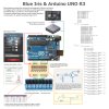
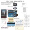
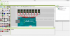
Virtual Bread Board for Arduino (VBB$ Arduino) Simulation Project sketch and screenshot further below:


import muvium.compatibility.arduino.Arduino;
class sketch_jun03a extends Arduino{ //Automatically Added VBB Framework Code - do not remove:
// Assign Arduino pin's that correspond to Blue Iris DIO Output functions and Set digital output bits for Camera alerts:
// Below table of Blue Iris digital output bits, their corresponding serial data sent to Arduino and the resulting anticipated actions when triggered:
//Alert bit bytes:action:eek:n bytes:action:eek:ff
//1 S01 S00
//2 S11 S10
//3 S01S11 S00S10
//4 S21 S20
//5 S01S21 S00S20
//6 S11S21 S10S20
//7 S01S11S21 S00S10S20
//8 S31 S30
//9 S01S31 S00S30
//10 S11S31 S10S30
//11 S01S11S31 S00S10S30
//12 S21S31 S20S30
//13 S01S21S31 S00S20S30
//14 S11S21S31 S10S20S30
//15 S01S11S21S31 S00S10S20S30
//16 S41 S40
//17 S01S41 S00S40
//18 S11S41 S10S40
//19 S01S11S41 S00S10S40
//20 S21S41 S20S40
//21 S01S21S41 S00S20S40
//22 S11S21S41 S10S20S40
//23 S01S11S21S41 S00S10S20S40
//24 S31S41 S30S40
//25 S01S31S41 S00S30S40
//26 S11S31S41 S10S30S40
//27 S01S11S31S41 S00S10S30S40
//28 S21S31S41 S20S30S40
//29 S01S21S31S41 S00S20S30S40
//30 S11S21S31S41 S20S30S40
//31 S01S11S21S31S41 S00S10S20S30S40
//32 S51 S50
//64 S61 S60
//128 S71 S70
//256 S81 Multiple S81
//512 S91 Multiple S91
//1024 S;1 Multiple S;1
// The onboard SMD LED on pin 13 is used by the optiboot loader on Arduino UNO and it is recommended not to be used as pre-mature or unintended cycle hi/lo during boot (the LED blinks a few times)
// which may pre-maturely or unintentionally activate and relays connected to pin 13 in a power-fail or initial connection to PC situation:
// If you use pin 13 for something else remove its OptionalControlPin13 configurations below:
static final int OptionalControlPin13 = 13; //OptionalControlPin13, assigns pin:
// Emulate Blue Iris in the simulation by entering S01,S00,S11,S10,S21,S20,S31,S30 in the console window:
static int OptionalControlPin13 = 13; //OptionalControlPin13, assigns pin:
static int DIOOutput1 = 11; // PWM:
static int DIOOutput2 = 10; // PWM:
static int DIOOutput3 = 9; // PWM:
static int DIOOutput4 = 8;
static int CAMAlert1 = 7;
static int CAMAlert2 = 6; //PWM
static int CAMAlert3 = 5; //PWM
static int CAMAlert4 = 4;
// With GCE Electronics selected as a protocol for serial port in Blue Iris Digital I/O settings sends three bytes for DIO Outputs controls as follows:
// DIO Output 1 Trigger on S01, off S00:
// DIO Output 2 Trigger on S11, off S10:
// DIO Output 3 Trigger on S21, off S20:
// DIO Output 4 Trigger on S31, off S30:
// Blue Iris Force option sends the on Bytes S01, S11, S21 and S31 but does not send the corresponding off bytes namely S00, S10, S20 and S30 when the force toggle is released
// Once releasing the Force option toggle then trigger the same DIO to "unlatch" the relevant DIO output.
// We need to create a variable for each byte to read incomming data into:
int Byte1; // incomming data value "S" will be read into this variable:
int Byte2; // incomming data value "0","1","2" or "3" will be read into this variable:
int Byte3; // incomming data value "0" or "1" will be read into this variable:
public void setup() {
// put your setup code here, to run once:
// initialize serial communication:
Serial.begin(9600);
// initialize the LED pin as an output:
pinMode(OptionalControlPin13, OUTPUT); //OptionalControlPin13, define pin 13 as output:
pinMode(DIOOutput1, OUTPUT);
pinMode(DIOOutput2, OUTPUT);
pinMode(DIOOutput3, OUTPUT);
pinMode(DIOOutput4, OUTPUT);
pinMode(CAMAlert1, OUTPUT);
pinMode(CAMAlert2, OUTPUT);
pinMode(CAMAlert3, OUTPUT);
pinMode(CAMAlert4, OUTPUT);
// for added safety, ensure all pins are initially low:
digitalWrite(OptionalControlPin13, LOW); //OptionalControlPin13,set pin 13 (and onboard LED off) low:
digitalWrite(DIOOutput1, 0);
digitalWrite(DIOOutput2, 0);
digitalWrite(DIOOutput3, 0);
digitalWrite(DIOOutput4, LOW);
digitalWrite(CAMAlert1, LOW);
digitalWrite(CAMAlert2, 0);
digitalWrite(CAMAlert3, 0);
digitalWrite(CAMAlert4, LOW);
}
public void loop() {
// put your main code here, to run repeatedly:
// see if there's incoming serial data greater than 2 bits as GCE serial outputs are three bits:
if (Serial.available() > 0) {
// read
Byte1 = Serial.read();
Byte2 = Serial.read();
Byte3 = Serial.read();
// Begin loop for DIO Output relays:
// if it's a S01 (ASCII), turn on full the LED PWM pin 11:
if (Byte1 == 'S' && Byte2 == '0' && Byte3 == '1') {
digitalWrite(DIOOutput1, 255);
}
// if it's a S00 (ASCII), turn off full the LED PWM pin 11:
if (Byte1 == 'S' && Byte2 == '0' && Byte3 == '0') {
digitalWrite(DIOOutput1, 0);
}
// if it's a S11 (ASCII), turn on full the LED PWM pin 10:
if (Byte1 == 'S' && Byte2 == '1' && Byte3 == '1') {
digitalWrite(DIOOutput2, 255);
}
// if it's a S10 (ASCII), turn off full the LED PWM pin 10:
if (Byte1 == 'S' && Byte2 == '1' && Byte3 == '0') {
digitalWrite(DIOOutput2, 0);
}
// if it's a S21 (ASCII), turn on full the LED PWM pin 9:
if (Byte1 == 'S' && Byte2 == '2' && Byte3 == '1') {
digitalWrite(DIOOutput3, 255);
}
// if it's a S20 (ASCII), turn off full the LED PWM pin 9:
if (Byte1 == 'S' && Byte2 == '2' && Byte3 == '0') {
digitalWrite(DIOOutput3, 0);
}
// if it's a S31 (ASCII), turn on the LED pin 8:
if (Byte1 == 'S' && Byte2 == '3' && Byte3 == '1') {
digitalWrite(DIOOutput4, HIGH);
}
// if it's a S30 (ASCII), turn off the LED pin 8:
if (Byte1 == 'S' && Byte2 == '3' && Byte3 == '0') {
digitalWrite(DIOOutput4, LOW);
}
// Begin loop for Camera alert output relays:
// Blue Iris "Set digital output bits" for camera alert set 16
// if it's a S41 (ASCII), turn on the LED pin 7:
if (Byte1 == 'S' && Byte2 == '4' && Byte3 == '1') {
digitalWrite(CAMAlert1, HIGH);
}
// if it's a S40 (ASCII), turn off the LED pin 7:
if (Byte1 == 'S' && Byte2 == '4' && Byte3 == '0') {
digitalWrite(CAMAlert1, LOW);
}
// Blue Iris "Set digital output bits" for camera alert set 32
// if it's a S51 (ASCII), turn on full the LED PWM pin 6:
if (Byte1 == 'S' && Byte2 == '5' && Byte3 == '1') {
digitalWrite(CAMAlert2, 255);
}
// if it's a S50 (ASCII), turn off full the LED PWM pin 6:
if (Byte1 == 'S' && Byte2 == '5' && Byte3 == '0') {
digitalWrite(CAMAlert2, 0);
}
// Blue Iris "Set digital output bits" for camera alert set 64
// if it's a S61 (ASCII), turn on full the LED PWM pin 5:
if (Byte1 == 'S' && Byte2 == '6' && Byte3 == '1') {
digitalWrite(CAMAlert3, 255);
}
// if it's a S60 (ASCII), turn off full the LED PWM pin 5:
if (Byte1 == 'S' && Byte2 == '6' && Byte3 == '0') {
digitalWrite(CAMAlert3, 0);
}
// Blue Iris "Set digital output bits" for camera alert set 128
// if it's a S71 (ASCII), turn on the LED pin 4:
if (Byte1 == 'S' && Byte2 == '7' && Byte3 == '1') {
digitalWrite(CAMAlert4, HIGH);
}
// if it's a S70 (ASCII), turn off the LED pin 4:
if (Byte1 == 'S' && Byte2 == '7' && Byte3 == '0') {
digitalWrite(CAMAlert4, LOW);
}
}
}
 
 
}


Attachments

Last edited by a moderator:

cds333

Young grasshopper
Joined
Jan 5, 2016
Messages
41
Reaction score
6
Forgive me but does this use a usb cable as alluded to in the graphic, or a serial cable? And does it use "Open DIO device on serial port" or the "Open Sealevel SeaDAC device" setting in BI?

Thanks!
 

Kevern

n3wb
Joined
Jun 27, 2015
Messages
28
Reaction score
11
USB cable between PC and Arduino, maps to a virtual Com port using Arduino driver, use settings below with whatever your com port mapped to.
You can also use SeaDac but it is a little more expensive.
~blue iris options.png

Forgive me but does this use a usb cable as alluded to in the graphic, or a serial cable? And does it use "Open DIO device on serial port" or the "Open Sealevel SeaDAC device" setting in BI?

Thanks!
 

Kevern

n3wb
Joined
Jun 27, 2015
Messages
28
Reaction score
11
Follow my posts below and use a serial port monitor, something like Eltima Serial Port Monitor, to see what code is being sent to/received from the Arduino.
Once you know what is being sent you can then debug your setup.
Also, just note that depending on what version of Blue Iris you have will vary the "Trigger with DIO input bit's" sent from BI to Arduino.
 

cds333

Young grasshopper
Joined
Jan 5, 2016
Messages
41
Reaction score
6
Great thanks so much. I am familiar with PICs but not with arduino; didn't know it has a built in USB-serial converter.
 

Kevern

n3wb
Joined
Jun 27, 2015
Messages
28
Reaction score
11
cds333.

Arduino does not have a built in USB-serial converter, the Arduino has a USB port, a USB cable connects the Arduino to a USB port on your computer, the windows driver (from the Arduino IDE installation package)for the Arduino creates a virtual com port to which "serial" data is sent.
In fact if you Load up the Arduino IDE (Integrated Development Environment) you will realize what I am talking about.

Great thanks so much. I am familiar with PICs but not with arduino; didn't know it has a built in USB-serial converter.
 

eeeeees

Young grasshopper
Joined
Jan 14, 2016
Messages
62
Reaction score
19
Hello Kevern

My goal is to have several PIRs (relay closure output on motion) initiate recording by blue iris. Several BI alerts would trigger relay closures. I am using a Terminal program for testing not BI yet. The sketch in post #7 compiles and runs just fine. Sending S70 & S71 turns pin 4 off & 0n perfectly. Things seem to be working.
I have not been able to find any input pins that when toggled will cause the arduino to output any code. Please point to the line numbers where this is effected.

Thanks for a good start for me.
Eric

Anybody else got ideas I got ears.
 

Kevern

n3wb
Joined
Jun 27, 2015
Messages
28
Reaction score
11
eeeeeees....

The code and the diagram are wrtitten for relay output control by either the DIO interface (on the BI App) or DIO output (on camera seetings), The Arduino, based on instructions recieved from BI, actuate the relays, this is evident in the code as "digitalWRITE" and "Output" are listed everywhere and there are no defined "INPUTS" or "0" so unfortunately I would not be able to show you the lines of code for inputs on the pins as there are none in the design.
However, I imagine you are using the PIR to assist in motion detection and then record the event etc. and the PIR is wired to provide an input into the Arduino, and the Arduino will trigger the relevant camera?
Personally, if I had enough camera's I would just use the motion detection masking on the camera to record the event and control the relay, ... but let me not digress...

To write code for an Arduino input, using Pin8 as an example; (and I am a little rusty here and writing this off the top of my head)
The concept in the code below should basically continually send S70 to BI if Pin8 > 3.3Vdc, you probably need to tidy it up a little and add your own count loop so that there will be only one S70 sent to BI for every X seconds the pin is high etc. etc.
A camera would have to be setup to listen for the alert trigger "S70" and then record.

public void setup(){
int val = 0; //Define variable for reading pin state value
static int INput4 = 8; //Define variable to Pin8
pinMode(INput4, INPUT); //Assign as input
}
public void loop() {
val = digitalREAD(INput4); //read the input state
if(val = 1){ //if it is above 3.3vdc do the following
Serial.write(S); //Write value to serial
Serial.write(7); //Write value to serial
Serial.write(0); //Write value to serial
}
}
 

vincenttor

Getting the hang of it
Joined
Oct 2, 2014
Messages
210
Reaction score
47
This looks great,
nicely done !
Wish i had the skills to write my own tools/scripts , have been looking for this for a while but i have another solution since i connected it with a plugin to my home automation software
But, if i would not have had this HA i would definitely tried your script !
 

eeeeees

Young grasshopper
Joined
Jan 14, 2016
Messages
62
Reaction score
19
Hello Kevern
It was my original intent to use video motion sensing but it didn't work out because of headlights on passing cars triggering things. May not be PIR, I just used that as an example, point is that I want to use a contact closure to initiate BI action.
I got it on missing that the sketch has no provision for inputs, my mistake. I got led astray by your post #6 above.

I tried to implement the code you provided but could not get it to compile. Its above my skill level.

Where to go from here?

On another thread I came across another sketch that purports to do exactly what I want. Four relays out, four DI inputs and GCE interface. I have attached an archive of this sketch _interface1-160120a.zip. I don't know who to credit it to. Long story short...... compiles and outputs work fine but the ASCII out is not correct. It puts out a null 00h and 01h for contact 1 and 02h for contact 2, etc and lotsa spare nulls on occasion. I see the 'S' in the sketch but no evidence of it on the ASCII going to BI.

There seems to be lots of posts with examples, about using Arduino's with BI but all seem deficient in some minor way. Any ideas out there besides send a few hundred $ to Sealevel.

Eric
 

Attachments

lotusandy

n3wb
Joined
Jul 26, 2015
Messages
7
Reaction score
1
Hello Kevern


On another thread I came across another sketch that purports to do exactly what I want. Four relays out, four DI inputs and GCE interface. I have attached an archive of this sketch _interface1-160120a.zip. I don't know who to credit it to. Long story short...... compiles and outputs work fine but the ASCII out is not correct. It puts out a null 00h and 01h for contact 1 and 02h for contact 2, etc and lotsa spare nulls on occasion. I see the 'S' in the sketch but no evidence of it on the ASCII going to BI.


Eric
Eric,

I am using the code you have zipped and it works fine for me with a PIR, as you mention it transmits a hex 01 for a contact closure & a hex 00 for a contact open, (it also transmits hex 00 every 20 seconds of so) this can then be used to trigger recording, alerts etc in BI. Blue iris will send a ascii S01 to allow the arduino to switch digital output 0 ON and ascii S00 to switch digital output 1 OFF etc.
So the zipped up code will work fine with an Arduino to allow you to trigger a camera channel via a pir or other contact closure....
Let me know if need further help

Andy
 

eeeeees

Young grasshopper
Joined
Jan 14, 2016
Messages
62
Reaction score
19
Hello Andy
Thank you very much for the response. Subsequent to my last post I figured it out for myself and the sketch now works well for me. I have two questions tho. Would you post screen shots of your BI Digital I/O and camera Motion/Trigger pages. I am still a little unsure about the optimum setup and could use some info on the BI side of the problem. If you are an ardunio coder type guy I would also like to know how to invert (low true instead of high true) the relay output on the sketch. Its trivial in hardware but over my head in the sketch. Do you know the source of the sketch? I like to give credit where it is due.

Thanks again for your reply.
Eric
 

lotusandy7

n3wb
Joined
Nov 13, 2015
Messages
7
Reaction score
1
Eric, Under options on the digital IO tab I have just ticked the open DIO device on serial port COM4 & set the protocal to GCE electronics.
on the camera motion/trigger tab I have checked the Trigger with DIO input bits 1 box.
The Arduino code was written by Dolby, here.
https://www.ipcamtalk.com/showthread.php/4201-Arduino-amp-Blue-Iris-Integration?highlight=arduino

I am not a coder but can hack code about when I need, the line that writes the logic states to the arduino output pins is
digitalWrite(myOutput, myState); so would could just invert myState before this line I guess?

good luck
 
Top