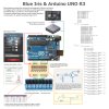
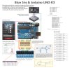
Virtual Bread Board for Arduino (VBB$ Arduino) Simulation Project sketch and screenshot further below:
import muvium.compatibility.arduino.Arduino;
class sketch_jun03a extends Arduino{ //Automatically Added VBB Framework Code - do not remove:
// Assign Arduino pin's that correspond to
Blue Iris DIO Output functions and Set digital output bits for Camera alerts:
// Below table of Blue Iris digital output bits, their corresponding serial data sent to Arduino and the resulting anticipated actions when triggered:
//Alert bit bytes:action

n bytes:action

ff
//1 S01 S00
//2 S11 S10
//3 S01S11 S00S10
//4 S21 S20
//5 S01S21 S00S20
//6 S11S21 S10S20
//7 S01S11S21 S00S10S20
//8 S31 S30
//9 S01S31 S00S30
//10 S11S31 S10S30
//11 S01S11S31 S00S10S30
//12 S21S31 S20S30
//13 S01S21S31 S00S20S30
//14 S11S21S31 S10S20S30
//15 S01S11S21S31 S00S10S20S30
//16 S41 S40
//17 S01S41 S00S40
//18 S11S41 S10S40
//19 S01S11S41 S00S10S40
//20 S21S41 S20S40
//21 S01S21S41 S00S20S40
//22 S11S21S41 S10S20S40
//23 S01S11S21S41 S00S10S20S40
//24 S31S41 S30S40
//25 S01S31S41 S00S30S40
//26 S11S31S41 S10S30S40
//27 S01S11S31S41 S00S10S30S40
//28 S21S31S41 S20S30S40
//29 S01S21S31S41 S00S20S30S40
//30 S11S21S31S41 S20S30S40
//31 S01S11S21S31S41 S00S10S20S30S40
//32 S51 S50
//64 S61 S60
//128 S71 S70
//256 S81 Multiple S81
//512 S91 Multiple S91
//1024 S;1 Multiple S;1
// The onboard SMD LED on pin 13 is used by the optiboot loader on Arduino UNO and it is recommended not to be used as pre-mature or unintended cycle hi/lo during boot (the LED blinks a few times)
// which may pre-maturely or unintentionally activate and relays connected to pin 13 in a power-fail or initial connection to PC situation:
// If you use pin 13 for something else remove its OptionalControlPin13 configurations below:
static final int OptionalControlPin13 = 13; //OptionalControlPin13, assigns pin:
// Emulate Blue Iris in the simulation by entering S01,S00,S11,S10,S21,S20,S31,S30 in the console window:
static int OptionalControlPin13 = 13; //OptionalControlPin13, assigns pin:
static int DIOOutput1 = 11; // PWM:
static int DIOOutput2 = 10; // PWM:
static int DIOOutput3 = 9; // PWM:
static int DIOOutput4 = 8;
static int CAMAlert1 = 7;
static int CAMAlert2 = 6; //PWM
static int CAMAlert3 = 5; //PWM
static int CAMAlert4 = 4;
// With GCE Electronics selected as a protocol for serial port in Blue Iris Digital I/O settings sends three bytes for DIO Outputs controls as follows:
// DIO Output 1 Trigger on S01, off S00:
// DIO Output 2 Trigger on S11, off S10:
// DIO Output 3 Trigger on S21, off S20:
// DIO Output 4 Trigger on S31, off S30:
// Blue Iris Force option sends the on Bytes S01, S11, S21 and S31 but does not send the corresponding off bytes namely S00, S10, S20 and S30 when the force toggle is released
// Once releasing the Force option toggle then trigger the same DIO to "unlatch" the relevant DIO output.
// We need to create a variable for each byte to read incomming data into:
int Byte1; // incomming data value "S" will be read into this variable:
int Byte2; // incomming data value "0","1","2" or "3" will be read into this variable:
int Byte3; // incomming data value "0" or "1" will be read into this variable:
public void setup() {
// put your setup code here, to run once:
// initialize serial communication:
Serial.begin(9600);
// initialize the LED pin as an output:
pinMode(OptionalControlPin13, OUTPUT); //OptionalControlPin13, define pin 13 as output:
pinMode(DIOOutput1, OUTPUT);
pinMode(DIOOutput2, OUTPUT);
pinMode(DIOOutput3, OUTPUT);
pinMode(DIOOutput4, OUTPUT);
pinMode(CAMAlert1, OUTPUT);
pinMode(CAMAlert2, OUTPUT);
pinMode(CAMAlert3, OUTPUT);
pinMode(CAMAlert4, OUTPUT);
// for added safety, ensure all pins are initially low:
digitalWrite(OptionalControlPin13, LOW); //OptionalControlPin13,set pin 13 (and onboard LED off) low:
digitalWrite(DIOOutput1, 0);
digitalWrite(DIOOutput2, 0);
digitalWrite(DIOOutput3, 0);
digitalWrite(DIOOutput4, LOW);
digitalWrite(CAMAlert1, LOW);
digitalWrite(CAMAlert2, 0);
digitalWrite(CAMAlert3, 0);
digitalWrite(CAMAlert4, LOW);
}
public void loop() {
// put your main code here, to run repeatedly:
// see if there's incoming serial data greater than 2 bits as GCE serial outputs are three bits:
if (Serial.available() > 0) {
// read
Byte1 = Serial.read();
Byte2 = Serial.read();
Byte3 = Serial.read();
// Begin loop for DIO Output relays:
// if it's a S01 (ASCII), turn on full the LED PWM pin 11:
if (Byte1 == 'S' && Byte2 == '0' && Byte3 == '1') {
digitalWrite(DIOOutput1, 255);
}
// if it's a S00 (ASCII), turn off full the LED PWM pin 11:
if (Byte1 == 'S' && Byte2 == '0' && Byte3 == '0') {
digitalWrite(DIOOutput1, 0);
}
// if it's a S11 (ASCII), turn on full the LED PWM pin 10:
if (Byte1 == 'S' && Byte2 == '1' && Byte3 == '1') {
digitalWrite(DIOOutput2, 255);
}
// if it's a S10 (ASCII), turn off full the LED PWM pin 10:
if (Byte1 == 'S' && Byte2 == '1' && Byte3 == '0') {
digitalWrite(DIOOutput2, 0);
}
// if it's a S21 (ASCII), turn on full the LED PWM pin 9:
if (Byte1 == 'S' && Byte2 == '2' && Byte3 == '1') {
digitalWrite(DIOOutput3, 255);
}
// if it's a S20 (ASCII), turn off full the LED PWM pin 9:
if (Byte1 == 'S' && Byte2 == '2' && Byte3 == '0') {
digitalWrite(DIOOutput3, 0);
}
// if it's a S31 (ASCII), turn on the LED pin 8:
if (Byte1 == 'S' && Byte2 == '3' && Byte3 == '1') {
digitalWrite(DIOOutput4, HIGH);
}
// if it's a S30 (ASCII), turn off the LED pin 8:
if (Byte1 == 'S' && Byte2 == '3' && Byte3 == '0') {
digitalWrite(DIOOutput4, LOW);
}
// Begin loop for Camera alert output relays:
// Blue Iris "Set digital output bits" for camera alert set 16
// if it's a S41 (ASCII), turn on the LED pin 7:
if (Byte1 == 'S' && Byte2 == '4' && Byte3 == '1') {
digitalWrite(CAMAlert1, HIGH);
}
// if it's a S40 (ASCII), turn off the LED pin 7:
if (Byte1 == 'S' && Byte2 == '4' && Byte3 == '0') {
digitalWrite(CAMAlert1, LOW);
}
// Blue Iris "Set digital output bits" for camera alert set 32
// if it's a S51 (ASCII), turn on full the LED PWM pin 6:
if (Byte1 == 'S' && Byte2 == '5' && Byte3 == '1') {
digitalWrite(CAMAlert2, 255);
}
// if it's a S50 (ASCII), turn off full the LED PWM pin 6:
if (Byte1 == 'S' && Byte2 == '5' && Byte3 == '0') {
digitalWrite(CAMAlert2, 0);
}
// Blue Iris "Set digital output bits" for camera alert set 64
// if it's a S61 (ASCII), turn on full the LED PWM pin 5:
if (Byte1 == 'S' && Byte2 == '6' && Byte3 == '1') {
digitalWrite(CAMAlert3, 255);
}
// if it's a S60 (ASCII), turn off full the LED PWM pin 5:
if (Byte1 == 'S' && Byte2 == '6' && Byte3 == '0') {
digitalWrite(CAMAlert3, 0);
}
// Blue Iris "Set digital output bits" for camera alert set 128
// if it's a S71 (ASCII), turn on the LED pin 4:
if (Byte1 == 'S' && Byte2 == '7' && Byte3 == '1') {
digitalWrite(CAMAlert4, HIGH);
}
// if it's a S70 (ASCII), turn off the LED pin 4:
if (Byte1 == 'S' && Byte2 == '7' && Byte3 == '0') {
digitalWrite(CAMAlert4, LOW);
}
}
}
}


