Blinking red LED in NVR board after firmware update

CA50

Young grasshopper
Joined
Sep 30, 2018
Messages
30
Reaction score
1
Location
India
Hi all,
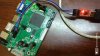
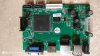
This is my first thread in this forum. Recently i purchased a NVR kit from ebay a 4CH 720P NVR Kit. (Hi3520 SoC)
I have done the setup, where NVR is connected to the router via LAN and the IP cameras are connected to the router via WiFi
I was unable to connect my IP camera to the NVR, but i was able to view live feed using my computer.

I googled and read that some have solved the problem with firmware update. Next searching for firmware i landed here 资源下载 - 尚维国际
First i used this :20180120-狮安-NVR6-S-2G16M-V1.0.1.7685 - 尚维国际
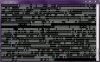
Result: NVR stuck in boot logo

Then i used this 20171012-狮安-NVR6-S-1G16M-v1.0.1.7246 - 尚维国际
Result: NVR was working fine, but still unable to find the network IP Camera

Next i flashed with this: 20180308-狮安-NVR6-S-16M2G-V1.0.1.7685 - 尚维国际
Result: After update the NVR restarted by no display. Only the red LED in the board is blinking and the front panel power LED is lit up.

I have tried the following but there is no success
1. removing the CMOS battery and HDD
2. connected USB keeping the previously working firmware
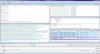
3. connected network cable, but the network LEDs are not working


I guess it is bricked, pleas share some inputs on how can i fix it.
 

Attachments

alastairstevenson

Staff member
Joined
Oct 28, 2014
Messages
15,970
Reaction score
6,795
Location
Scotland
pleas share some inputs on how can i fix it.
It's pretty likely the bootloader is still working, though there may be problems with the main firmware.

Suggestion:
The serial console will give useful information on the status and problems, and should allow some recovery options.
See if you can connect up to the serial console, using a serial TTL to USB convertor, usually a PL2303HX-based one works OK.
Looking at the board - I'd guess that J18, behind the RJ45 connector, provides the serial console connections.
Don't touch the 5v pad. The Tx and Rx are likely to be the middle 2 pads.
 

CA50

Young grasshopper
Joined
Sep 30, 2018
Messages
30
Reaction score
1
Location
India
Thank you for your input. J18 seems to be a 5V output.
I checked with multimeter and J6 seems to be the serial pads. Currently i am using an arduino to read the serial data. But the serial output is blank.

The same arduino configuration is working fine with my router, I am able to read the serial data.
 

CA50

Young grasshopper
Joined
Sep 30, 2018
Messages
30
Reaction score
1
Location
India
Yes, that does look similar to J18.


Why do you think J6 is the serial and not J18? Do the pads under the label have markings?
Remember that the serial TTL outputs stay at either 3.3 or 5v when not sending data.
In J18, Voltage at Pin #2 and #3 is 0.01 (~0). Only at the 5V pad its 5V
But in J6, Pin 1, 2 and 3 has ~3.3V and pin 4 is the ground
 

alastairstevenson

Staff member
Joined
Oct 28, 2014
Messages
15,970
Reaction score
6,795
Location
Scotland
In J18, Voltage at Pin #2 and #3 is 0.01 (~0). Only at the 5V pad its 5V
But in J6, Pin 1, 2 and 3 has ~3.3V and pin 4 is the ground
That makes sense, I think you are right.

So not output at all? Not good.
 

CA50

Young grasshopper
Joined
Sep 30, 2018
Messages
30
Reaction score
1
Location
India
That makes sense, I think you are right.

So not output at all? Not good.
Sadly yes, there is no output.
The red LED keeps on blinking, i have connected another LED in the buzzer pad, that too keeps on blinking.

My only option is to try with a PL2303HX / CP2102 UART converter
 

CA50

Young grasshopper
Joined
Sep 30, 2018
Messages
30
Reaction score
1
Location
India
A small update. I tried with 2 USB-to-TTL converter based on PL2303 and CP2102.
In both the case, i can read garbage data.

I also found that when the GND of USBTTL is connected to GND of the NVR, no data is read. When when it is removed i can read garbage.
 

alastairstevenson

Staff member
Joined
Oct 28, 2014
Messages
15,970
Reaction score
6,795
Location
Scotland
So it is generating data, but not yet clear.

Dumb questions, for which apologies :
It would be correct to have the two GNDs connected.
115,200 baud with 8 bits no parity?
And trying a few lower baud rates such as 9600 and 19,200?
And you have tried the Rx of the convertor on both pins 2 and 3?

**Edit** I'm not familiar with that convertor - definitely detail TTL and not RS232 ?
 

CA50

Young grasshopper
Joined
Sep 30, 2018
Messages
30
Reaction score
1
Location
India
It would be correct to have the two GNDs connected.
- When i do it nothing is displayed on the console

115,200 baud with 8 bits no parity?
- Yes I am using that

And trying a few lower baud rates such as 9600 and 19,200?
And you have tried the Rx of the convertor on both pins 2 and 3?
- Tried both the these, but no solution

These are the connectors which I am using
https://www.amazon.in/USB-TTL-ADPT-Serial-Machine-Upgrade-Adapter/dp/B006JKNWLE/ref=sr_1_5?s=computers&ie=UTF8&qid=1538507942&sr=1-5&keywords=Cp2102
https://www.amazon.in/PL2303HX-Convert-RS232-Converter-Module/dp/B07CR9LNBH/ref=sr_1_1?s=electronics&ie=UTF8&qid=1538508197&sr=1-1&keywords=PL2303HX
 
Top