Sure looks like you've found the answer. If you're able to swap the transformer and get the camera fixed I'll consider that a victory for the good guys, as the saying goes. I personally don't have a very good record working with the new micro geometries and SMDs, probably having destroyed more than I've fixed. Back in the days of tenth-inch grids I was a soldering whiz.
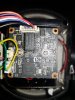
Having said the important things, my OCD is screaming that there's something fishy going on, in that the power should have never appeared on the green and orange pairs. Looking at the power/data combiner adapter:
View attachment 74605
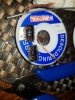
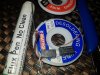
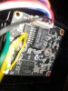
I believe (and told you earlier) that the data exits the adapter on the orange/green pairs, and power on blue/brown. Then looking at the ali express combiner:
View attachment 74606
Both of the male RJ45s should connect to pins 1,2,3,6, where the green/orange pairs normally connect to. I think I can see that in the picture. Therefore, power should have been not connected at this point, and the power should have never been sent down the long ethernet cable.
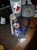
So now I'm wondering if that first power/combiner adapter is scrambling the pin assignments in a way I think they shouldn't? If the accompanying splitter on the other end is compatible it doesn't matter, but with the ali express splitter in the middle, what you're seeing would happen.


.jpg")