**FIXED** Complete newby, damage to RJ45 connector!

Jan 25, 2020
22
9
New Jersey
So,

I’m new to all of this, I am pretty tech savvy for the most part but I am stumped. I have a 8ch 1080p SANNCE NVR wireless system, came with 4 cameras paired to NVR, i was considering changing interface so I was changing the camera ip’s to my network’s gateway, well silly me conflicted the first camera, so it umpired. No biggie, I just plug the Ethernet into camera and square it away, when I attempted to do so, I realize the RJ45 network connector was chewed up and missing one, had to have came with that, and when I attempted to call I was talking to a brick wall, then I went to email support for assistance but the email was returned, needless to say I gave up on that, so I watched a video where the guy cut the connector off, put a male end on the wires, attached to female coupler and had Ethernet connect to router. But I can not for the life of me find a Pinout or any diagrams, I had to rush out of the door and my dogs ruined any chance of knowing what wires were what. I do however, have a couple pictures.

every post I see has color wires I don’t. I only have to connect to router to resolve IP issue then it’s back to wireless. Anybody have any beginner friendly advice? And trust me, I already ordered other cameras so I just hate to see the thing just sit in a bin, and It’s more for the learning experience

the wires are:
Purple
Blue
White/Blue
Green
White/Green
Black
Red

in that order, no orange, no brown, no grey. And I don’t know if I just have other end as same order or how that works

**UPDATE** I fixed it, was tired of searching for the right answer and used logic, if all I was seeking was Ethernet power, then worry about the RJ45 wires so I just used the 4 wires and let the rest dangle, Blue/White - Pin 1, Blue - Pin 2, Green/White - Pin 3, Green - Pin 6, worked like a charm.
 

Attachments

  • 3A498885-E190-4E0F-B66C-85DAAD1F7EC2.jpeg
    3A498885-E190-4E0F-B66C-85DAAD1F7EC2.jpeg
    1.5 MB · Views: 67
  • AC7B5124-9961-44A8-9D2E-CD921BABCA3F.jpeg
    AC7B5124-9961-44A8-9D2E-CD921BABCA3F.jpeg
    1.9 MB · Views: 71
  • A2481B40-0521-4A2E-82EE-8FB797AE28D5.jpeg
    A2481B40-0521-4A2E-82EE-8FB797AE28D5.jpeg
    998.3 KB · Views: 69
  • 41B82DE9-8B08-431B-AAE0-9336E9EBBE64.jpeg
    41B82DE9-8B08-431B-AAE0-9336E9EBBE64.jpeg
    1 MB · Views: 65
  • 51A72DAC-EB43-4A56-ADAD-8CE3ABF243AE.jpeg
    51A72DAC-EB43-4A56-ADAD-8CE3ABF243AE.jpeg
    955.4 KB · Views: 64
  • 0E8DDEAD-2E0B-44BC-9273-4C844D40CE45.jpeg
    0E8DDEAD-2E0B-44BC-9273-4C844D40CE45.jpeg
    1 MB · Views: 58
Last edited:
  • Like
Reactions: Parley and mat200
If the RJ-45 female is still attached to the pigtail can't you skin back enough of the overall outer jacket to see each of the wires, cut one at a time, use continuity checker / ohm meter to check which wire goes to which pin, write it down, do another one, etc. and label the pigtail accordingly?

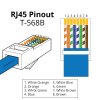
You could then crimp on a RJ-45 male or punch down a RJ-45 female jack, just insure that you locate pin 1 to be on left when facing female jack and latch is on bottom (pin 1 on right when looking at end of MALE and latch on bottom).

EDIT: I'm not implying that you follow any color code here such as T-568B, I'm saying that whatever colored conductor you find on pin 1 of YOUR bad RJ-45 connector would go to pin 1 of the new connector and so on.


RJ45-Pinout-T568B_med.jpg
 
Last edited:
So,

I’m new to all of this, I am pretty tech savvy for the most part but I am stumped. I have a 8ch 1080p SANNCE NVR wireless system, came with 4 cameras paired to NVR, i was considering changing interface so I was changing the camera ip’s to my network’s gateway, well silly me conflicted the first camera, so it umpired. No biggie, I just plug the Ethernet into camera and square it away, when I attempted to do so, I realize the RJ45 network connector was chewed up and missing one, had to have came with that, and when I attempted to call I was talking to a brick wall, then I went to email support for assistance but the email was returned, needless to say I gave up on that, so I watched a video where the guy cut the connector off, put a male end on the wires, attached to female coupler and had Ethernet connect to router. But I can not for the life of me find a Pinout or any diagrams, I had to rush out of the door and my dogs ruined any chance of knowing what wires were what. I do however, have a couple pictures.

every post I see has color wires I don’t. I only have to connect to router to resolve IP issue then it’s back to wireless. Anybody have any beginner friendly advice? And trust me, I already ordered other cameras so I just hate to see the thing just sit in a bin, and It’s more for the learning experience

the wires are:
Purple
Blue
White/Blue
Green
White/Green
Black
Red

in that order, no orange, no brown, no grey. And I don’t know if I just have other end as same order or how that works

Hi @Breakrellom

The RJ45 connector photo is out of focus, can you retake it and share it?

Thanks

1579971756029.png
 
I posted this when I had to repair the pigtail on a Dahua camera. I double-checked the pin out with a voltmeter and found it to be the same with what others had come up with before. Notice how only two pairs of the four pairs of wires are 'twisted'? (they were also wrapped in foil which acts like a shield). These are going to be your transmit and receive pair so that should help you narrow things down
Pig Tail Repair.jpg
 

Attachments

  • TRI-572.jpg
    TRI-572.jpg
    80.3 KB · Views: 40
Last edited:
  • Like
Reactions: mat200
I posted this when I had to repair the pigtail on a Dahua camera. I double-checked the pin out with a voltmeter and found it to be the same with what others had come up with before. Notice how only two pairs of the four pairs of wires are 'twisted'? These are going to be your transmit and receive pair so that should help you narrow things down
View attachment 54562

FYI - I suspect the Sannce camera maybe a Hikvision OEM or other OEM, not Dahua. Not completely certain as I've only found limited links when searching for the model Sannce I31v

1579972559269.png
 
**UPDATE** I fixed it, was tired of searching for the right answer and used logic, if all I was seeking was Ethernet power, then worry about the RJ45 wires so I just used the 4 wires and let the rest dangle, Blue/White - Pin 1, Blue - Pin 2, Green/White - Pin 3, Green - Pin 6, worked like a charm.
 
If this ever helps anyone. Wiring up an old Sannce PoS fake POE camera. Pay attention to the wire colors, if they are not the same as mine, you may have issues. I have no idea what model it is, but seems to be of the same generation 2015-2017. Please note the grey is not used for ethernet, but an led on a connector along with one of the black wires (likely the thin black, pin 7). In any case, I had to cut it off a working one to figure out their stupid wiring arrangement. This is what worked for me.

ethernet to Sannce junk
pin1 - stripe orange
pin2 - orange
pin3 - stripe green
pin4 - red
pin5 - thick red
pin6 - green
pin7 - black
pin8 - thick black
 
  • Like
Reactions: TonyR
If this ever helps anyone. Wiring up an old Sannce PoS fake POE camera. Pay attention to the wire colors, if they are not the same as mine, you may have issues. I have no idea what model it is, but seems to be of the same generation 2015-2017. Please note the grey is not used for ethernet, but an led on a connector along with one of the black wires (likely the thin black, pin 7). In any case, I had to cut it off a working one to figure out their stupid wiring arrangement. This is what worked for me.

ethernet to Sannce junk
pin1 - stripe orange
pin2 - orange
pin3 - stripe green
pin4 - red
pin5 - thick red
pin6 - green
pin7 - black
pin8 - thick black
Amazingly, that color code corresponds (except DC + and - colors) to T-568B, 10/100, Mode B and for passive POE as here.
Your Reds are DC + and your Blacks are DC-.

Sannce-sPOE.jpg
 
Amazingly, that color code corresponds (except DC + and - colors) to T-568B, 10/100, Mode B and for passive POE as here.
Your Reds are DC + and your Blacks are DC-.

View attachment 178059
Excellent. The grey was the variable, until i saw the little green led indicator on the boot. I also had a hard time getting and rj45 connector on due to the thickness of the red and black DC. It's obvious now, but their wires are super thin and trying to test it out was frustrating to say the least. I hope it helps someone trying the same thing.
 
  • Like
Reactions: TonyR
Excellent. The grey was the variable, until i saw the little green led indicator on the boot. I also had a hard time getting and rj45 connector on due to the thickness of the red and black DC. It's obvious now, but their wires are super thin and trying to test it out was frustrating to say the least. I hope it helps someone trying the same thing.
Did the cam have a 12VDC power jack in addition to the RJ-45 female?