
I think I Bricked it?
- Thread starter msp116
- Start date
You are using an out of date browser. It may not display this or other websites correctly.
You should upgrade or use an alternative browser.
You should upgrade or use an alternative browser.
EMPIRETECANDY
IPCT Vendor

Yes the camera powers on, but no I CANNOT access the web interface. It tries to communicate with the switch then after about 5-10 sec it goes out and starts all over again. How or where would I communicate with it over a serial connection?Now the camera can't access from webpage? Still can ping the IP? Can try to make a hard reset and test again.
If camera can be powered and can't access from webpage, camera bricked. Need ftp to do serieal port flash to bring the camera back
EMPIRETECANDY
IPCT Vendor
A successor of Dahua IPC unbricking / recovery over serial UART and TFTP
I recommend you to read through the above thread first.
If your camera still has a working bootloader (assume it does) then you can flash it easily, because:
The camera tries to download a file called "upgrade_info_7db780a713a4.txt" from a TFTP server running on 192.168.254.254 and executes the commands in said file in the bootloader (U-Boot) shell.
For more in-depth information, read this post: Dahua Firmware Mod Kit + Modded Dahua Firmware
Step 1, Configuring the network correctly.
The cameras IP...

Just refer to this link.
I really appreciate....can you confirm what is the latest working firmware for this?I didn't realize I tried to upload a US version firmware...A successor of Dahua IPC unbricking / recovery over serial UART and TFTP
I recommend you to read through the above thread first.
If your camera still has a working bootloader (assume it does) then you can flash it easily, because:
The camera tries to download a file called "upgrade_info_7db780a713a4.txt" from a TFTP server running on 192.168.254.254 and executes the commands in said file in the bootloader (U-Boot) shell.
For more in-depth information, read this post: Dahua Firmware Mod Kit + Modded Dahua Firmware
Step 1, Configuring the network correctly.
The cameras IP...
Just refer to this link.
Attachments
tigerwillow1
Known around here
Ok so Im stumped I have tried every connection I could find in the turret and in the housing. The only place I seem to get anything is the 4 pin connector under the top housing of the unit see pic....the other 3 pin connector on the turret next to the SD card and reset switch has a jumper on it...I tried checking it with a meter but get nothing...anybody out there have any other ideas I'm open to suggestions.....


Still never got this to work couldn't locate correct pins....if anybody is interested in trying to fix this would be willing to ship and pay if they are successful in unbricking it....I just don't have the time and there are plenty of people on here way smarter than me at this....Tks for any help in advance!!
To be honest you are looking in the wrong place. That board there is the Power board for the camera body Housing in some cases you might find access to a data port in the housing but that isn't where the issue is. The issue is in the camera where the FW that you meant to upload failed to work and has bricked your camera. All happy dance in the Housing has nothing to do with the camera being alive. IN a PTZ there is the Power board by taking the top off if you will I will call the area that connects to Mount Arm the top, Then there is a Center Control board. This is where there are connection going to Pan and Tilt motors, in some will have temp sensor and heater in there as well. These 2 boards work even if you took out the Camera module. It will do the dance anyway as that is what the housing is designed to do. Then if the camera was working correctly once the camera came online and if someone logged in or NVR sent control commands to the camera the camera would then talk with the housing to do the pan and tilt while the zoom is cameras business alone..
So When you do an update or fail to do one that data lives in the camera module. This part will need to be removed and 9 times out of 10 you will need to remove the Main Camera module PCB from the cage. This will be taking out 2 or 4 screws that hold the cage together. THen there will be 2 maybe 4 screws that hold in the zoom lens to the camera PCB. The data area is on the Modules main PCB, Not the cameras PCB, there will be a PCB inside that cage
Now question is how does one work on these.. Well truth if if you don't work on these cameras and don't have a Power station setup for these cameras then you will need to gain access to the next level of the housing where the Motor wires are connected and you will want to disconnect the Pan and Tilt Wires. This way the camera isn't doing the dance when you power it on.. Then you will need to remove the wires that is going to the head area where the camera module lives, Normally just 1 screws maybe 2 on the side of the head that is holding wires and hall effect sensor to the unit. Anyway once you remove the wires from the housing you will now be able to plug the wires into the cameras PCB from the module. Normally to keep the PCB from touching the zoom motors I will put a paper towel between the PCB and zoom lens. you will need to have access to the PCB and won't have access with it in the head or in the cage so it will need to be taken apart.. Then to access you will need to put the camera back to the main PCB and connect the zoom lens back to main PCB, Then connect the wires like you are installing back in camera housing but the wires are just laying on the desk.. Now once it is all powered up again with pan and tilt wires removed from center PCB you will have access to the cameras main brain..
I don't know your camera, I have worked on enough of these PTZs to know they are all built about the same when it comes to how these are laid out.. For the last 4 PTZ that I repaired 3 2mp and 1 4mp they all had same layout in the housing 1 was wifi as well as POE and so it had extra wiring running into the head for the wifi connection to the cameras main PCB.. the 25x camera had little larger zoom lens and little larger camera module PCB but the layout and design was the same. So seeing they were Dahua my guess is it will be same for your camera besides there will be an extra wire setup for the wiper motor other then that the cameras module cage will need to be removed from the head of the camera..
To get the camera module out, Without looking at the camera my guess is same as with my camera. 4 scews on the back of the camera head, then maybe a PCB with reset button and Micro SD card with 3 screws and all the heads wires. Heater, fan, IR, In your case Wiper Motor wires, camera control wires. They all need to come off the board. Then remove the Gel Packs on the right and left side of the head, Careful seeing normally they are tight and taped in. Once you get that out you will have 4 scews, Before you remove the screws I would take out the cameras wires, these are wires coming in from main body and not part of the mess that was on that first PCB.. 3 wire sets 2 on the back and one on the side, Be careful with one on the side, Normally a few wires maybe 3 or 4 on a 6 to 8 pin and if the camera is older might be brittle and the connecter might break. Once that is removed those are the wires you will need to pull from the head for working on the camera at the bench. Only the wires that were connected to the camera module. If you happen to have same number connectors mark them either different color or different side of connector so you remember what one goes where.. I use different color sharpie.. If only 1 color, 1 and 2 dot system and side of connecter for wires.. Meaning 2 dots on right side of connector and same 2 dots on the wires harness then on the other one 1 dot on each side and same for harness this way will know what goes where..
Once you get the module out and the PCB out of the cage, In my case all the cameras even with different size PCB had the data port in a 4 via square area. One of them just looked like it was going to nothing because it running on an inner layer of the PCB.. Other one could just follow to the chip as the traces were on the top layer of the PCB.. Once you get your TX and RX your golden.
alastairstevenson
Staff member
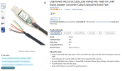
Did you buy a 'USB to TTL serial' adaptor?I purchased the UART cable.
The 4-pin connector that you tried is most likely the serial UART.
This Is the one I purchased....Did you buy a 'USB to TTL serial' adaptor?
The 4-pin connector that you tried is most likely the serial UART
Attachments
DAHUA SD8C848PA1-HNF thanks for the AWESOME relpy/help. I will attempt your suggestion ASAP.....finger crossed!To be honest you are looking in the wrong place. That board there is the Power board for the camera body Housing in some cases you might find access to a data port in the housing but that isn't where the issue is. The issue is in the camera where the FW that you meant to upload failed to work and has bricked your camera. All happy dance in the Housing has nothing to do with the camera being alive. IN a PTZ there is the Power board by taking the top off if you will I will call the area that connects to Mount Arm the top, Then there is a Center Control board. This is where there are connection going to Pan and Tilt motors, in some will have temp sensor and heater in there as well. These 2 boards work even if you took out the Camera module. It will do the dance anyway as that is what the housing is designed to do. Then if the camera was working correctly once the camera came online and if someone logged in or NVR sent control commands to the camera the camera would then talk with the housing to do the pan and tilt while the zoom is cameras business alone..
So When you do an update or fail to do one that data lives in the camera module. This part will need to be removed and 9 times out of 10 you will need to remove the Main Camera module PCB from the cage. This will be taking out 2 or 4 screws that hold the cage together. THen there will be 2 maybe 4 screws that hold in the zoom lens to the camera PCB. The data area is on the Modules main PCB, Not the cameras PCB, there will be a PCB inside that cage
Now question is how does one work on these.. Well truth if if you don't work on these cameras and don't have a Power station setup for these cameras then you will need to gain access to the next level of the housing where the Motor wires are connected and you will want to disconnect the Pan and Tilt Wires. This way the camera isn't doing the dance when you power it on.. Then you will need to remove the wires that is going to the head area where the camera module lives, Normally just 1 screws maybe 2 on the side of the head that is holding wires and hall effect sensor to the unit. Anyway once you remove the wires from the housing you will now be able to plug the wires into the cameras PCB from the module. Normally to keep the PCB from touching the zoom motors I will put a paper towel between the PCB and zoom lens. you will need to have access to the PCB and won't have access with it in the head or in the cage so it will need to be taken apart.. Then to access you will need to put the camera back to the main PCB and connect the zoom lens back to main PCB, Then connect the wires like you are installing back in camera housing but the wires are just laying on the desk.. Now once it is all powered up again with pan and tilt wires removed from center PCB you will have access to the cameras main brain..
I don't know your camera, I have worked on enough of these PTZs to know they are all built about the same when it comes to how these are laid out.. For the last 4 PTZ that I repaired 3 2mp and 1 4mp they all had same layout in the housing 1 was wifi as well as POE and so it had extra wiring running into the head for the wifi connection to the cameras main PCB.. the 25x camera had little larger zoom lens and little larger camera module PCB but the layout and design was the same. So seeing they were Dahua my guess is it will be same for your camera besides there will be an extra wire setup for the wiper motor other then that the cameras module cage will need to be removed from the head of the camera..
To get the camera module out, Without looking at the camera my guess is same as with my camera. 4 scews on the back of the camera head, then maybe a PCB with reset button and Micro SD card with 3 screws and all the heads wires. Heater, fan, IR, In your case Wiper Motor wires, camera control wires. They all need to come off the board. Then remove the Gel Packs on the right and left side of the head, Careful seeing normally they are tight and taped in. Once you get that out you will have 4 scews, Before you remove the screws I would take out the cameras wires, these are wires coming in from main body and not part of the mess that was on that first PCB.. 3 wire sets 2 on the back and one on the side, Be careful with one on the side, Normally a few wires maybe 3 or 4 on a 6 to 8 pin and if the camera is older might be brittle and the connecter might break. Once that is removed those are the wires you will need to pull from the head for working on the camera at the bench. Only the wires that were connected to the camera module. If you happen to have same number connectors mark them either different color or different side of connector so you remember what one goes where.. I use different color sharpie.. If only 1 color, 1 and 2 dot system and side of connecter for wires.. Meaning 2 dots on right side of connector and same 2 dots on the wires harness then on the other one 1 dot on each side and same for harness this way will know what goes where..
Once you get the module out and the PCB out of the cage, In my case all the cameras even with different size PCB had the data port in a 4 via square area. One of them just looked like it was going to nothing because it running on an inner layer of the PCB.. Other one could just follow to the chip as the traces were on the top layer of the PCB.. Once you get your TX and RX your golden.
Looking at your first picture again.. Looking at the ARM chip did you happen to check if that data port going to that chip also might work the one in the camera head? Might be able to do it all from that area without having to take the camera apart save you an hour of tear down time.. Can you give me the ARM chip number I will look up the data sheet for the chip and see if it has the ability to do it from there and save you some time. Depending on the chip it might need some extra software like STM32CUBEProgrammer, or Flash Magic. But it could save you loads of time?
alastairstevenson
Staff member
That's an RS-485 adaptor.This Is the one I purchased....
For the serial console, you'll need a TTL serial adaptor, such as a PL2303TA-based one.