
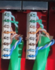
I have an IP camera that I want to use for license plate recognition. So I put a new Ethernet cable into the patch panel and created my own Ethernet connector on the other side of the cable which connects to the camera. However, I cannot see the camera using SADPTool (for testing I am using a Hickvision cam as it's laying outside on the floor but the final camera will be a Dahua from Andy). SADPTool has no problem seeing any of the other cameras. So clearly I am doing something wrong, most likely with the cabling. On the camera side I used 568B. But then I checked the patch panel that was done by a professional (I copied his outline) and I see that white green = pin 1, green = pin 2, white orange = pin 3, orange = pin 4, white brown = pin 5, brown = pin 6, white blue = pin 7, blue = pin 8. That neither matches 568A nor 568B. Is the patch panel manufacturer just routing signals differently on the PCB? And if so, how do I know if they use 568A for 568B?
IP Camera Wiring
- Thread starter rfj
- Start date
You are using an out of date browser. It may not display this or other websites correctly.
You should upgrade or use an alternative browser.
You should upgrade or use an alternative browser.

tangent
IPCT Contributor
- May 12, 2016
- 4,641
- 3,999
Look a the silkscreen on the PCB and see what it says. It's hard to see in your picture, what looks like a faint "1" is visible. The question is: is the silk screen labeled 1-8 in order or do the number jump around?
If you can't visually follow the traces and figure it out, use a multimeter in ohm or continuity mode to figure out the relationship between the block and the RJ-45 (you can make a breakout cable of sorts it it helps).
If you can't visually follow the traces and figure it out, use a multimeter in ohm or continuity mode to figure out the relationship between the block and the RJ-45 (you can make a breakout cable of sorts it it helps).
fenderman
Staff member
- Mar 9, 2014
- 36,890
- 21,419
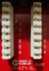
Then the panel is wired T-568A.It is a CableMatters but I don't know the model. Maybe E188100 (based on the picture). Anyways, now that I look at some unused ports (again, see attached image) it seems the pins are not in sequence. They are 1, 2, 3, 6, 7, 8, 5, 4.
If it were T-568B then the G/W & G pair on 1/2 would be swapped with the O/W & O pair on 3/6
fenderman
Staff member
- Mar 9, 2014
- 36,890
- 21,419
Its not wrong, just use the 568B on the patch panel.Ah, so I wired the camera wrong because I did 568B and the camera side.
tigerwillow1
Known around here
Maybe I'm missing something obvious? As long as the cable from the patch panel to the camera is wired the same on both ends, it doesn't matter if the patch panel is A or B.
fenderman
Staff member
- Mar 9, 2014
- 36,890
- 21,419
It does not. But both of his ends did not match.Maybe I'm missing something obvious? As long as the cable from the patch panel to the camera is wired the same on both ends, it doesn't matter if the patch panel is A or B.

Griswalduk
Known around here
Iirc wiring one end 568A and the other end 568B creates a cross-over cable.

It does but if the switch portion of the network devices are rated Auto MDI/MDX as mentioned by @tangent , it still should work.Iirc wiring one end 568A and the other end 568B creates a cross-over cable.
That being said, it's best practice to make up both ends the same and in the U.S. of A. the predominate spec is T-568B.
@TonyR Indeed, as you said in post #5, the patch panel is T-568A. And as you said in post #12 it was my understanding that in the USA we usually use T-568B. So I wired the camera end to T568B (not because of your post but because of what I read up before) while on the patch panel I followed what was done before (T-568A). I did redo the cable on the camera side and now it works. Thank you all very much for the feedback.
For the curious and the interested, some info and history from Wikipedia ==>>T568A and T568B termination