Looking to add an alarm to Dahua NVR but have no experience with this.

Sunny7

Young grasshopper
Joined
Aug 22, 2019
Messages
58
Reaction score
21
Location
US
Hey all, I'm looking to add an alarm to my Dahua brand NVR but I have no experience with alarms or the whole wiring thing. I'd like to have some bit of noise whenever something triggers my camera's IVS rules so I set my NVR to buzzer whenever something is triggered and I was pretty disappointment at how bad it was. It just gives the most pathetic 2 silent little beebs I've never heard, I guess they don't want you to disturb the people breaking into your home.

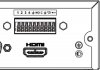
So I want to add an alarm output, I guess, to my NVR but I don't know where or what to look for in an alarm. Like, I can use just any alarm? My Dahua NVR model is a 4208-8P-4KS2 if that helps. I've read the Dahua wiki and the wiring seems simple enough, a ground wire would go into the ground port and the other wire goes into the numbered ports? Also one last dumb question, what are Input alarms? I saw input and output alarms in the pdf manual and got mixed up a bit.
 

Fastb

Known around here
Joined
Feb 9, 2016
Messages
1,342
Reaction score
934
Location
Seattle, Wa
The "Alarm" signal is a dry contact. The alarm pin will be open (float) or will be connected to ground. This signal can control a seperate alarm. Don't assume the "Alarm" can drive a speaker, that would be a completely seperate kind of thing.

The Alarm In signal the NVR expects is similar. The input floats. The NVR looks for the "Alarm input" signal to become grounded. It's configurable if the alarm is activatted with the ground signal or not--gnd signal.

Alarm inputs - Not working

use this as a serch term in google:
site:ipcamtalk.com, alarm input, nvr
 

tigerwillow1

Known around here
Joined
Jul 18, 2016
Messages
3,816
Reaction score
8,424
Location
USA, Oregon
Is this your back panel?

4208.jpg
If it is, two of the contact pins are brought out for each of the two alarm output relays. "C" is for common, and "N" is for normally open. The normally closed relay contacts are not wired. My belief is that C and N are both floating (i.e. not internally connected to ground or anything else).
If you don't have a recent manual one can be pulled from here . I don't know if it the latest or not, which is always difficult for me to figure out. I also don't know offhand what the relay contact ratings are. Maybe a spec sheet would list that. If I was close to or above 50% of the rating I'd personally have it drive another mechanical or solid state relay, just because I'd rather not fry something soldered to the motherboard.

As to an alarm, you want something that makes noise when power is applied to it, or when some trigger wire is activated. Pretty much anything where connecting 2 wires together causes it to make sound. You have to supply the power for the alarm.
 

Sunny7

Young grasshopper
Joined
Aug 22, 2019
Messages
58
Reaction score
21
Location
US
Is this your back panel?

View attachment 68365
If it is, two of the contact pins are brought out for each of the two alarm output relays. "C" is for common, and "N" is for normally open. The normally closed relay contacts are not wired. My belief is that C and N are both floating (i.e. not internally connected to ground or anything else).
If you don't have a recent manual one can be pulled from here . I don't know if it the latest or not, which is always difficult for me to figure out. I also don't know offhand what the relay contact ratings are. Maybe a spec sheet would list that. If I was close to or above 50% of the rating I'd personally have it drive another mechanical or solid state relay, just because I'd rather not fry something soldered to the motherboard.

As to an alarm, you want something that makes noise when power is applied to it, or when some trigger wire is activated. Pretty much anything where connecting 2 wires together causes it to make sound. You have to supply the power for the alarm.
This is my rear panel for my 4208-8P-4KS2 model.

3463464.jpg

I couldn't find my exact model on a more recent pdf manual I had but the pdf you linked had it.
 

Attachments

Sunny7

Young grasshopper
Joined
Aug 22, 2019
Messages
58
Reaction score
21
Location
US
Ok so I spent some time trying to find an alarm and ended up finding the one from the video @djernie linked since that one is pretty cheap and none of the others I found never let's you listen to them online.

Not sure if this will help or not.
Kind of, the video goes a bit too fast but for my set up based on my pic of my back panel, if I get everything from the video 12v adapter + power jack connector + alarm I don't really need that lego adapter thingy? So I would have a alarm wire going into one of the ports(green arrow) while the ac wire going into the ground(blue arrow)?

IMG_20200814_031838084_HDR_2.jpg
 
Joined
Jul 31, 2018
Messages
1,306
Reaction score
2,468
Location
texas
Ok so I spent some time trying to find an alarm and ended up finding the one from the video @djernie linked since that one is pretty cheap and none of the others I found never let's you listen to them online.


Kind of, the video goes a bit too fast but for my set up based on my pic of my back panel, if I get everything from the video 12v adapter + power jack connector + alarm I don't really need that lego adapter thingy? So I would have a alarm wire going into one of the ports(green arrow) while the ac wire going into the ground(blue arrow)?

View attachment 68827
Let us know if it works out.
 

Sunny7

Young grasshopper
Joined
Aug 22, 2019
Messages
58
Reaction score
21
Location
US
Let us know if it works out.
I haven't ordered my equipment or done much yet due to leg injury but I'm still trying to figure stuff out before I do anything so again I'm completely new at wiring stuff and so a lot of this stuff is going over my head as I still don't get the difference between the Normally Open(NO) and Common ports(C). The wiki or google doesn't help because everyone's rear panel and set up is different than mine. If I used this alarm + adapter and go for a simple set up like this

Untitled.png

Do I use the numbered ports or the NO/C ports? Because I'm seeing too many different set ups and I'm getting confused.
 
As an Amazon Associate IPCamTalk earns from qualifying purchases.
Joined
Jul 31, 2018
Messages
1,306
Reaction score
2,468
Location
texas
From this video it looks like you will use the NO/ports which from your drawing is the first two ports after the number 4. The two port under the C i am going to assume are for Normally Closed connections. In the video they connect the positive from the adapter to a relay which i think on your DVR the 1234 ports are relay. So you will plug the positive from your adapter to 1 and the positive from your alarm to the NO port. Now keep in mind i have never done this because i do not use an nvr. But if i was doing it i would just try different things until i got it to work. And yes the ports on the video dvr are different from yours but they function the same. Good luck!
 

Sunny7

Young grasshopper
Joined
Aug 22, 2019
Messages
58
Reaction score
21
Location
US
My alarm and stuff finally came in.

From this video it looks like you will use the NO/ports which from your drawing is the first two ports after the number 4. The two port under the C i am going to assume are for Normally Closed connections. In the video they connect the positive from the adapter to a relay which i think on your DVR the 1234 ports are relay. So you will plug the positive from your adapter to 1 and the positive from your alarm to the NO port. Now keep in mind i have never done this because i do not use an nvr. But if i was doing it i would just try different things until i got it to work. And yes the ports on the video dvr are different from yours but they function the same. Good luck!
This makes sense. Trying to set this up now but ran into a small issue, the wire pins don't seem to be long enough to fit into the back of my NVR's or at least I think its not long enough.

IMG_20200825_242352354_HDR.jpg

The red cable is from my alarm and the orange cable with the long pin is a random jumper cable to connect the 12v power to the NVR. For my rear panel, I'm suppose to just push one of those tiny grey buttons hard and insert the pin? Because whenever I try it, it just spits the jumper pin out and the alarm's pin definitely isn't going in like it should. Wondering if I need to open up my NVR or strip the wire some more.
 

Fastb

Known around here
Joined
Feb 9, 2016
Messages
1,342
Reaction score
934
Location
Seattle, Wa
That looks like half of the connector. The terminal block portion is missing.
The terminal block is easily removed. It's a snap fit to the back of the NVR.
It has screws to tighten onto your cable's conductor. No need to crimp on pins to connect to NVR.

This is my experience, for my Dahua NVR. (model # in signature, bottom)

1598372630558.png
 

tigerwillow1

Known around here
Joined
Jul 18, 2016
Messages
3,816
Reaction score
8,424
Location
USA, Oregon
That looks like half of the connector. The terminal block portion is missing.
I was ready to hit the "post" button saying the same thing, then scrolled up and looked and the pictures in posts 5,6, 8 and 10. It looks like Dahua has maybe switched to the push-to-release type of connector on some of the models. If they have, I consider it a step backwards.
 

Fastb

Known around here
Joined
Feb 9, 2016
Messages
1,342
Reaction score
934
Location
Seattle, Wa
tigerwillow1, I think you're onto something. Push-to-release connectors may be used as a cost-reduction initiative....
 
Joined
Jul 31, 2018
Messages
1,306
Reaction score
2,468
Location
texas
I was ready to hit the "post" button saying the same thing, then scrolled up and looked and the pictures in posts 5,6, 8 and 10. It looks like Dahua has maybe switched to the push-to-release type of connector on some of the models. If they have, I consider it a step backwards.
So he should be able to push them in and it should work right?
 
Joined
Jul 31, 2018
Messages
1,306
Reaction score
2,468
Location
texas
My alarm and stuff finally came in.


This makes sense. Trying to set this up now but ran into a small issue, the wire pins don't seem to be long enough to fit into the back of my NVR's or at least I think its not long enough.

View attachment 69239

The red cable is from my alarm and the orange cable with the long pin is a random jumper cable to connect the 12v power to the NVR. For my rear panel, I'm suppose to just push one of those tiny grey buttons hard and insert the pin? Because whenever I try it, it just spits the jumper pin out and the alarm's pin definitely isn't going in like it should. Wondering if I need to open up my NVR or strip the wire some more.
i would try to make them longer and see if they do not get pushed back out.
 

tigerwillow1

Known around here
Joined
Jul 18, 2016
Messages
3,816
Reaction score
8,424
Location
USA, Oregon
So he should be able to push them in and it should work right?
I have these push-to-release connectors on sprinkler controllers. They're great for setting up the wiring quickly, not so great for reliability, especially the smaller versions. I built a couple of project boards using the small versions and ended up replacing them with screw type connectors. You should be able to look into the connector to see the metal blade that captures the wire, which gives a hint on how long the bare wire needs to be. I suggest pressing the insertion tab fully with an appropriate size flat-blade screwdriver, inserting the wire, releasing the tab, then giving the wire a good tug to see if it's really captured. If it doesn't pull out and you can see some bare wire exposed, the connection should be as good as it's going to get. I'd guess that the short pin in post #10 might work and the long pin should definitely work. If things aren't right look inside the hole for the wire with a flashlight, press the tab, and see if the connection blade looks undamaged and springs back fully.
 

Sunny7

Young grasshopper
Joined
Aug 22, 2019
Messages
58
Reaction score
21
Location
US
Yeah its a push type, I can see why its not liked. I'm scared I might break those little grey buttons how fragile they seem and how hard I need to push it. Here's another better pic, you can see the 3rd from the right looks damaged because its the one I've been messing with the most.
IMG_20200825_194503500_HDR.jpg

i would try to make them longer and see if they do not get pushed back out.
So that means I would need to solder another pin on top of the jumper and alarm pins? Man I really don't feel like hunting down the tools for this.:sleepy:

Eventually I decided to take a look inside the NVR to get an idea what to look and feel for.

IMG_20200825_192755469_HDR.jpg
Top left is the circuit board for the alarm part of the NVR . There's 2 screws on each end holding it up(the 2nd one is covered up behind those wires). I tried unscrewing it but its locked in tight as if its glued or soldered in or something and don't know if I really can get it to unscrew so I wasn't able to get it off and can't really get a good look at the alarm's board.

What a pain. So basically .8mm isn't long enough of a pin to reach the alarm on the NVR from the sound of it.
 
Joined
Jul 31, 2018
Messages
1,306
Reaction score
2,468
Location
texas
Yeah its a push type, I can see why its not liked. I'm scared I might break those little grey buttons how fragile they seem and how hard I need to push it. Here's another better pic, you can see the 3rd from the right looks damaged because its the one I've been messing with the most.
View attachment 69301


So that means I would need to solder another pin on top of the jumper and alarm pins? Man I really don't feel like hunting down the tools for this.:sleepy:

Eventually I decided to take a look inside the NVR to get an idea what to look and feel for.

View attachment 69305
Top left is the circuit board for the alarm part of the NVR . There's 2 screws on each end holding it up(the 2nd one is covered up behind those wires). I tried unscrewing it but its locked in tight as if its glued or soldered in or something and don't know if I really can get it to unscrew so I wasn't able to get it off and can't really get a good look at the alarm's board.

What a pain. So basically .8mm isn't long enough of a pin to reach the alarm on the NVR from the sound of it.
wow that sucks. I would still try making those wires longer and just test it. good luck
 

tigerwillow1

Known around here
Joined
Jul 18, 2016
Messages
3,816
Reaction score
8,424
Location
USA, Oregon
If the connector is the size I perceive from the picture, I'd push the release buttons with as large as possible screwdriver that fits inside the recess. Probably a jewelers screwdriver.
 

Sunny7

Young grasshopper
Joined
Aug 22, 2019
Messages
58
Reaction score
21
Location
US
wow that sucks. I would still try making those wires longer and just test it. good luck
Yeah I'll probably do that when I have the time. I was wondering if a small paperclip would work just to measure how far down into the alarm port I would need just to get a good measurement.

If the connector is the size I perceive from the picture, I'd push the release buttons with as large as possible screwdriver that fits inside the recess. Probably a jewelers screwdriver.
Yeah I've been using a screwdriver the whole time and pressing it until its all the way down or as much as I can. Those black covers on the jumper wire(don't know what you call them) keeps me from going any further. The alarm port holes just isn't big enough for the jumper wire to go through. I can feel, probably the tip, going in but it spits the jumper wire back out. The alarm wire is ever stranger, I don't feel anything when I stick it in which leads me to believe the pin on it is just too small.
 
Top