Hi,
I have a Lorex LNB8105X and I accidentally tripped on the wire, the camera connector was pulled out.
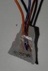
As you see on the connector (female) on picture #1 the only thing I know for sure, is that the blue wire is on connector 6. If you look at picture #2, you will see what I am working with. I tried the wiring presented in pictures #3 and 4 that correspondS to the pinout map of picture #5 and it did not work.
I tried to pull gently on each of the 6 wires, just in case one of them would have broken when I tripped on the wire, none of them came out.
I called Lorex and they will not "reveal" the pinout info.
I feel I am in a dead end. Can someone shed some light on this situation?
Thanks,
Michel
Picture #1

Picture #2

Picture #3

Picture #4

Picture #5

I have a Lorex LNB8105X and I accidentally tripped on the wire, the camera connector was pulled out.
As you see on the connector (female) on picture #1 the only thing I know for sure, is that the blue wire is on connector 6. If you look at picture #2, you will see what I am working with. I tried the wiring presented in pictures #3 and 4 that correspondS to the pinout map of picture #5 and it did not work.
I tried to pull gently on each of the 6 wires, just in case one of them would have broken when I tripped on the wire, none of them came out.
I called Lorex and they will not "reveal" the pinout info.
I feel I am in a dead end. Can someone shed some light on this situation?
Thanks,
Michel
Picture #1
Picture #2
Picture #3
Picture #4
Picture #5