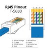
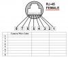
Thanks for the response. I did cut back the old female connector and can confirm the pinout sequence identified from Gordon Beall's thread (who also cut open the connector): 8/7=Grey, 6=Blue, 5/4=Yellow, 3=Orange, 2=Purple, 1=Brown. Then, using a heat gun and tiny self-soldering wire connectors, spliced a "y" to double up the Grey and Yellow pins. I used a lighter to expose the end of those thin wires as strippers proved useless. I want to test to make sure the splice and pinout was correct. I'm a bit afraid to just plug into NVR and "hope" it's correct as I'm nervous it may fry my NVR port if not correct. I have a tester that came with
Crimping tool and I'll see what that'll do. Anyway, I'll report back in case this thread can help someone else.
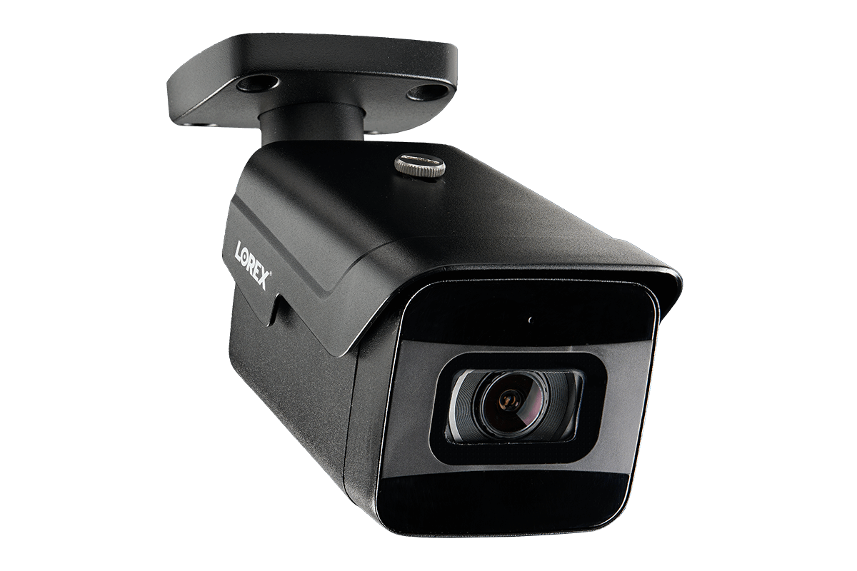
As a side note: I previously ordered a new replacement camera that LOREX claimed is compatible with my NVR but the new "Smart IP" cameras don't seem as smart as my current model and sends alerts non-stop (every 4 minutes) regardless to the Thresholds and Sensitivity settings for that camera. I hope the old camera works and can return the "smart" new one!!!