Mean Well power supply for POE+ Switch

Jan 1, 2024
763
351
USA
Anyone know of 52v mean well close in size to my current dead power supply that is 5 3/4 × 2 3/4 in. It is for a 8 port POE plus switch. Currently repairing it, waiting for parts stage for this one but really would like to repair and keep this as backup and use one that isn't 12 years old already. I mean this switch is from 2013. Going to have my son take the 16port switch from my NW property and send it to me so I can make sure it's not ready to fail. Think bought that one in 2016 no fan in switch and no AC in security closet it has to be close to fail. I'll swap out for my dahua PFS 3010 8 port poe+ switch. Seeing only 6 cameras are connected the others are poe nvr connected..

Anyway I did test this switch with my lab power supply and switch still works with working power supply. So worse case will just use power supply it had, but really would like to upgrade.
 

Attachments

  • 20250211_040154.jpg
    20250211_040154.jpg
    616.7 KB · Views: 0
There's no part number on it?

Lots of open frame Meanwells of different sizes, watts, volts here.
 
  • Like
Reactions: Revo2Maxx
So my switch PSU is repaired. I got tired of my china parts that have fallen off the face of the earth so I had to buy different part to repair because it don't seem anyone has the part I needed in USA. So paid for only the 2 I needed at 2 times the cost but I know they are real, no extras for backup but ended up buying 2, Toshiba TK18A50D STA4,Q,M and is N-Ch Mosfet 18A 500v 50..

Was going to buy a new Meanwell and had the right size unit but thought geez they already charging the Extra cost for the Tariff and thought wait why should I have to pay for that now when they didn't pay for it to start with. I know you have to replace what is sold but that extra cost should come after the fact not on products that there was no tariff.. I mean it was only 10 bucks extra but 80c for each Mosfet seemed better to me then paying 10 bucks for the next person to get a better deal. I am not paying someone tax that wasn't paid for to start with..

So for now the old PSU is back in and the POE+ switch is in and working again.. I did my first burn in test for 8 ports of under 15w. Now I am going to do 4 hour test with 4 POE+ loads and 4 normal POE loads. Once that passes I will do the full 8 port remove and restore power 10 to 20 times to make sure there is no other issues before I call it 100% completed repair..
 
Only 2 of my cameras on this switch support 1000, rest are 10/100 and the one without poe is going 1000m switch this switch is free air so I do kind of worry at max so only 4 ports running AT, 3 AF and one to data switch seeing this one don't have unlink port..

Edit, changed picture to reflect data going to gigabit switch, and change text to reflect change. Before was just going to 10/100 switch port.
 

Attachments

  • 20250408_210747.jpg
    20250408_210747.jpg
    673.8 KB · Views: 0
Last edited:
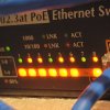
So I ran a stress test and did my off and on test and the power supply held up.. So I thought I would post my final thoughts for others that might take on the task of repairing a POE+ Switch. Reason i wanted to repair this one is that it is not only a POE+ it is a Giga POE+ switch and works well with the few Giga POE cameras that I own from Uniview and Alibi..

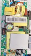
When repairing a switching power supply like this PoE+ 8-port unit, sometimes you're forced to substitute a different MOSFET if the original part is hard to get, like the JCS13N50FT. In this case, I used TK18A50D parts from Mouser, and the repair held up well through a proper burn-in test. That said, there are a few things to keep in mind if you're using a part that's not an exact match.

The first thing to consider is the gate charge, or Qg. A part with a significantly higher gate charge can switch more slowly, which not only reduces efficiency but can also lead to excess heat and potential overstress on the gate driver circuit. It’s something that’s easy to overlook, but in tightly tuned flyback supplies, timing matters more than you might think.

Another spec that can trip people up is RDS(on), or the drain-source on-resistance. If the part you choose has a much higher value than the original, it’s going to run hotter during operation, especially under load. Fortunately, the TK18A50D actually has a lower RDS(on) than the original JCS13N50FT, so in this case it’s actually an upgrade in terms of conduction loss.

Switching speed,, that is, how fast the MOSFET can turn on and off is also a big factor in power supply behavior. If the replacement part is significantly slower, you can end up with longer transition times, more heat, and maybe even oscillation or noise in the supply. It’s worth checking the rise and fall times in the datasheet to make sure you’re in the same ballpark.

The safe operating area, or SOA, is another spec that doesn’t always get the attention it deserves. If the replacement part has a weaker SOA than the original, it might not survive the voltage and current spikes that happen during normal operation. especially at startup or when the load suddenly changes. The TK18A50D has a good SOA for this kind of application, but it’s still worth confirming.

And finally, always make sure the voltage rating matches. In this case, both parts are 500V rated, so there’s no concern about breakdown from high-voltage flyback spikes.

The key thing is not to just match the Vds and current rating and call it a day. It’s important to consider how the part will behave in the real-world circuit, particularly how it switches, how much heat it generates, and how much stress it can take. After swapping the parts, a burn-in test is crucial. That gives you a solid check that the replacement is handling everything the power supply throws at it under actual load.

So to anyone else making a repair like this, don’t just drop in a “close enough” part. Compare gate charge, RDS(on), switching behavior, and SOA, and make sure your driver circuit is still up to the task. If all those check out, you’ve got a solid chance of a long-lasting repair.

And one last thing, be safe. These supplies operate at dangerous voltages, and the risks are real. If you're not completely confident working around high voltage circuitry, it's best to step back and find someone qualified to handle the repair. When in doubt source it out.
 
For this setup, I powered on the repaired power supply for the first time without any load connected, using a dim bulb tester to protect it in case there was still a short or some issue I missed during board level troubleshooting. I do have an old 1520 Variac that I could’ve used if I really needed to, but for this situation, I didn’t see the need to bring it in especially for just confirming the initial power up of the supply after repairs. My goal was to make sure the power supply was solid before reinstalling it in the switch, since I had already verified the switch itself worked fine using my bench power supply.

This particular PoE+ gigabit switch uses a different power supply design than the other PoE+ switches I own from the same brand, so I wanted to take small, careful steps to avoid damaging anything beyond the power supply itself. With the power supply still out of the switch and connected through the dim bulb setup, I turned it on. The bulb lit briefly, then went out exactly what I wanted to see. I used my meter to confirm that the output voltage was correct. With that confirmed, I disconnected the dim bulb and installed the power supply back into the switch.

Once everything was reassembled, I powered the switch back on without connecting anything to it, just to make sure it would start up cleanly. I didn’t use the dim bulb this time since both the power supply and switch had already proven themselves in isolation, and I wasn’t expecting any surprises. I also didn’t bother with the Variac since the switch is designed for 100–240V input and I’m running it on 120V, there wasn’t much point in gradually ramping up the voltage.

After confirming the switch powered on properly, I plugged in a PoE camera I didn’t mind sacrificing just in case something went wrong but it powered up just fine. From there, I continued testing using only 802.3af PoE cameras. Since the switch doesn’t have an uplink port, I initially connected it to one of my 24 port 10/100 PoE switches. But after an hour of stable operation, I switched it over to the gigabit switch as originally intended and connected some PoE devices that required full gigabit bandwidth.

I finished testing with four PoE+ devices and three standard PoE devices all running at once. No issues, no overload indicators, and the switch behaved just like it did on day one. The only thing that had me concerned throughout the process was using different MOSFETs than the originals even though I made sure the specs were the same or close enough to be compatible. Also, since this switch is a free air cooled unit, I kept an eye on potential heat issues, but so far, everything is running cool and stable.