Need help with RS232 pin-outs for DVR - HCVR5108H (OEM version, no Dahua logo) Mini 1U HDCVI

texpo

n3wb
Joined
Jun 15, 2018
Messages
8
Reaction score
0
Location
Canada
Hello,

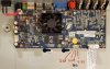
I have a Dahua OEM DVR that won't boot or display anything on the monitor (black screen). I see a red light on the main board where it marked LED4, so I suspect something is wrong with the firmware or programming. I read somewhere that I may have a chance to revive it with RS232, but I need help figuring out which pin is TX and RX. On the main board there is location where it is stamped RS232 and it did not have any pin headers or even a JST connector soldered to it. I de-soldered the JST connector that was originally for the USB on the front panel and soldered it to the RS232 pin-holes. I measured each pin with my multimeter and I got the following:

Pin 1 - 2.4V - 2.7 (not always constant)
Pin 2 - 3.3V
Pin 3 - GND
Pin 4 - 4.9V

I am planning on buying a USB-TTL PL2303TA / RS232 console cable to use but I don't know which pin is TX or RX.

Any other suggestions or guidance is appreciated. Thank you in advance!
 

Attachments

alastairstevenson

Staff member
Joined
Oct 28, 2014
Messages
15,930
Reaction score
6,778
Location
Scotland
On the main board there is location where it is stamped RS232 and it did not have any pin headers or even a JST connector soldered to it.
Odd that it's labelled RS232 when you've measured voltages that are normally associated with serial TTL.
RS232 uses different signalling standards.

Suggestion :
With your serial TTL to USB convertor, connect it's GND to the GND you've identified as Pin 3.
Connect the RX of the serial TTL convertor to Pin 1 of the header.
As you've identified that the voltage is always lower than 3.3v, that won't damage the RX input, unlike if you were to connect the TX to an output or power supply pin.
Using a serial terminal such as PuTTY, using 115,200 baud rate, 8 bits no parity, power cycle the DVR and hopefully see some serial console activity,
If you do so - it confirms that Pin 1 is serial console TX, and it should be safe to connect the TX of the serial TTL convertor to Pin 2.
A serial console RX will have an internal pullup resistor to 3.3v, so seeing that voltage with nothing connected is normal.

If you've not yet bought the serial TTL to USB convertor, maybe consider buying more than one as they are quite easily damaged by incorrect connections.
 

texpo

n3wb
Joined
Jun 15, 2018
Messages
8
Reaction score
0
Location
Canada
I meant to also mention -
If no data appears using RX on Pin 1, then try Pin 2.
And if that shows data, connect TX to Pin 1.
I bought the USB-TTL PL2303TA cable today, connected the black wire (GND) to pin 3 (GND) and the white wire (RX) to either pin 1 (2.4V > 2.6V) or pin 2 (constant 3.3V), power up the DVR and PuTTY just sits at a black screen. Windows 10 recognizes the cable and assigns it COM3. The comm port was set to 115,200 baud rate, 8 bits, parity none, stop bits 1, flow control none. So if data is not being received then does that mean the bootloader is bad?
 

Attachments

texpo

n3wb
Joined
Jun 15, 2018
Messages
8
Reaction score
0
Location
Canada
@alastairstevenson

Okay, so I concluded that the USB-TTL PL2303TA cable is working with a loopback test (connecting a piece of wire between RxD and TxD) in PuTTY 0.78, Termite 3.4, or MobaXterm 22.0 via local echo. So I guess this DVR is a goner unless there is anything else I could try?
 

texpo

n3wb
Joined
Jun 15, 2018
Messages
8
Reaction score
0
Location
Canada
Probably, unless that header isn't a serial console access point.
Last night I had only the white wire (Rx) connected to pin 2 (3.3V) and nothing else connected, not even GND and when I power on and off the DVR, PuTTY would start filling rows of blocks. So not sure if that is normal and it stops when I turn off the DVR which means pin 2 must be the (Tx) on the DVR?

EDIT:
Nevermind, it's not repeating the same thing this morning so it was just a random occurrence.
 
Last edited:

tech_junkie

Getting comfortable
Joined
Sep 2, 2022
Messages
412
Reaction score
417
Location
South Dakota
Last night I had only the white wire (Rx) connected to pin 2 (3.3V) and nothing else connected, not even GND and when I power on and off the DVR, PuTTY would start filling rows of blocks. So not sure if that is normal and it stops when I turn off the DVR which means pin 2 must be the (Tx) on the DVR?

EDIT:
Nevermind, it's not repeating the same thing this morning so it was just a random occurrence.
Its most likely a UART standard.
I'm a little curious why they didn't solder in the reset switch (K1).
Most failure LED are from insufficient power. Does it boot w/o a drive connected and/or the power supply substituted?
 

texpo

n3wb
Joined
Jun 15, 2018
Messages
8
Reaction score
0
Location
Canada
Its most likely a UART standard.
I'm a little curious why they didn't solder in the reset switch (K1).
Most failure LED are from insufficient power. Does it boot w/o a drive connected and/or the power supply substituted?
It does not boot w/o a drive and I tried using a different 12V, 2A power adapter as well. It powers on with a solid red light on LED4 and no POST beeps from the mini speaker.
 

tech_junkie

Getting comfortable
Joined
Sep 2, 2022
Messages
412
Reaction score
417
Location
South Dakota
Have you tried resetting it (shorting out K1 leads, then apply power, keep k1 shorted 30 seconds after power up, it should beep when default programming has been loaded, then remove jumper) ?
 

texpo

n3wb
Joined
Jun 15, 2018
Messages
8
Reaction score
0
Location
Canada
Have you tried resetting it (shorting out K1 leads, then apply power, keep k1 shorted 30 seconds after power up, it should beep when default programming has been loaded, then remove jumper) ?
I soldered a tactile push button to K1 and shorted it for 30 seconds after power apply power and no beep.
 
Top