RJ-45 PinOut for Dahua Bullet Camera

Alaska Country

Getting comfortable
Joined
Jun 10, 2021
Messages
449
Reaction score
657
Location
Alaska
What is the RJ-45 pin out for a Dahua camera (HFW 2831 and HFW 5242) Both IP cameras should be the same.

It appears that that each CAT 5/6 pair is tied together as indicated in the below diagram. Pins 1/2 are POE minus with pins 3/6 a POE plus. i.e. pin out also confirmed with CAT 5/6 cable tester.

POE-Pin-Out-Dahua.jpg

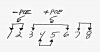
What is confusing is that normally data RX is on pins 1/2 and data TX on pins 3/6 as a standard. Is Dahua placing POE over data on the same pairs of wire? Or are they using pins 4/5 and 7/8 for data?

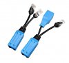
The reason for asking, is I would like to tap into the POE lines and power a POE to 12 VDC splitter with 48 VDC while at the same time powering the camera at 48 VDC. i.e. the splitter does not pass through the 48 VDC POE.

The concern is that if data is also on the POE line, then that data could be subject to loss (attenuation).

Thank you,

Jim
 
Last edited:

tigerwillow1

Known around here
Joined
Jul 18, 2016
Messages
3,851
Reaction score
8,528
Location
USA, Oregon
To comply with the POE standard, the camera must support both Mode A (power on the data wires 1,2,3,6, and pins 4,5,7,8 unused) and Mode B (power on 4,5,7,8). Which mode to used is decided by the Power Sourcing Equipment, and the Powered Device must support both. In the majority of cases, POE switches use Mode A, and POE injectors use Mode B. Successfully tapping the power with Mode A would take a pretty high level of the right technical knowledge. There are a few splitters out there that pass the power through to the camera. They've been pointed out on the forum a few times and the lowest cost one I remember seeing is in the forty-something dollar ballpark. Sorry I don't have a link for it handy. Somebody else probably does.
 

Alaska Country

Getting comfortable
Joined
Jun 10, 2021
Messages
449
Reaction score
657
Location
Alaska
Appreciate your comments. Looks like Dahua 5242 uses POE over data which adds an additional level of complexity.

In the above diagram, pins 1/2 and 3/6 appear to be shorted together, but are most likely either side of a transformer as shown in the below image.

PoE and IEEE 802 3.png

Overall, it looks like the simple soultion is to run a seperate two wire line for the 12 VDC mic and leave it at that. Modifying the splitter for 48 VDC POE pass through without the necessary components would be a real chore.

One last question. If pins 1/2 and 3/6 are data/POE then what does Dahua use pins 4/5 and 7/8 for?

Thank you,

Jim
 

alastairstevenson

Staff member
Joined
Oct 28, 2014
Messages
15,965
Reaction score
6,795
Location
Scotland
One last question. If pins 1/2 and 3/6 are data/POE then what does Dahua use pins 4/5 and 7/8 for?
As indicated by @tigerwillow1 in post #2, they are used for PoE also - depending on the PoE mode of the power sourcing device.

I would like to tap into the POE lines and power a POE to 12 VDC splitter with 48 VDC while at the same time powering the camera at 48 VDC. i.e. the splitter does not pass through the 48 VDC POE.
It looks like you are aware that, depending on how you do the parallel connection, you are likely to compromise the ethernet signals integrity.

An alternative approach would be to use the PoE splitter normally, such that it passes the data through, and split the 12v DC for both the camera and microphone.
 

Alaska Country

Getting comfortable
Joined
Jun 10, 2021
Messages
449
Reaction score
657
Location
Alaska
Just tapping into the 48 volt line would effect the data signal levels something that I would rather not do. It would perhaps even reduce the data levels to non usable IMO. However, one could try to add an RF choke (inductor), as a tap, with a calculated value depending on the overall data rate (frequency) to help decrease data signal loss.

Tried to determine the voltages present on the NVR with a CAT-5e breakout box. However, basically voltages are not present.

Assuming, that in order see the 48 volts on 4/5 and 7/8 it will be necessary to terminate 4/5 and 7/8 into a resistance so that the NVR will see that the connection is not open.

Any suggested value for a resister to be placed across pins 4 and 5 plus pins 7 and 8? Or what is the minimum current needed for the NVR to determine that the circuit is live? i.e. 10 mA which would be a 4.8 K ohm resistor.

Also would assume that it would not be possible to use both 1/2 and 3/6 (for data over POE) at the same time as 4/5 and 7/8 (for POE only). If possible, then using a POE splitter and POE injector kit would separate out 1/2/3/6 from 4/5/7/8.

Splitter-Injector.jpg

Overall, would like to avoid using 12 volts for camera power with a 48 volt to 12 volt converter as adding the splitter introduces another possible point of failure.
 

tigerwillow1

Known around here
Joined
Jul 18, 2016
Messages
3,851
Reaction score
8,528
Location
USA, Oregon
Also would assume that it would not be possible to use both 1/2 and 3/6 (for data over POE) at the same time as 4/5 and 7/8 (for POE only). If possible, then using a POE splitter and POE injector kit would separate out 1/2/3/6 from 4/5/7/8.
I have a few runs where I split out 4/5/7/8 for a separate camera. In one case I use the split-out 4/5/7/8 to power only a 12-volt IR illuminator via a POE splitter. Eats up a switch port to do this.
 

Alaska Country

Getting comfortable
Joined
Jun 10, 2021
Messages
449
Reaction score
657
Location
Alaska
I do have extra non used NVR camera ports, so will keep this in mind.

My overall issue, is to not run more wires for 12 volt power. May have to try splitting out 1/2/3/6 to run the splitter and 4/5/7/8 to run the camera on the same camera NVR port. Not sure if that will work or not. The other option is to use one NVR camera port for the camera say 4/5/7/8 and use another camera NVR port using 1/2/3/6 for the splitter and combined on a single CAT-5e cable.
 
Top