RJ45 Wiring connector order

chrisc90

Young grasshopper
Joined
Oct 28, 2018
Messages
48
Reaction score
1
Location
UK
Hi all

Just a post to see if any other people have struggled sticking a male RJ45 on the end of a hikvision lead.

Ive done it in the past and was successful. Another of our cameras suffered corroded pins inside the female connector on the hikvision lead. So did some end to end testing with the plug inside the camera to determine the cause.

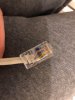
Chopped the female plug off and proceeded to wire the connecter in as per the documentation on hikvision site:
Didnt work. Double checked all wires, end to end connectivity incase bad crimp, but all good. Tried again and again. but nothing.

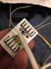
Then got a RJ45 wall socket adapter which has the RJ45 colour codes on the reverse and matched the colours on the wall socket adapter to the correct colour on the camera wire using the table...ignoring the pin layout they mention.

I ended up with:

Pin 8: White
Pin 7: Brown
Pin 6: Yellow
Pin 5: Grey
Pin 4: Purple
Pin 3: Orange
Pin 2: Blue
Pin 1: Green

No idea why the documentation they provide is wrong....but I not have a bad headache.

Anyone else found this?
 

Attachments

alastairstevenson

Staff member
Joined
Oct 28, 2014
Messages
15,970
Reaction score
6,795
Location
Scotland
No idea why the documentation they provide is wrong
It's not wrong -
Presumably you are making the right choice between Pro series and Value series?
This is from my notes, where I've replaced a fair few damaged pigtails on Hikvision cameras :

Code:
This is a cross-reference from the T568B RJ45 pinouts to the Hikvision connectors.
Note - on the later (G1) cameras, Hikvision have swapped pins 4 and 5 (Grey and Purple).

T568B                Hik cable           
1    orange/white    1    orange           
2    orange          2    yellow           
3    green/white     3    green           
4    blue            4    grey           
5    blue/white      5    purple           
6    green           6    blue           
7    brown/white     7    brown           
8    brown           8    white           
                     9
                     10
                     11    12v outer       
                     12    12v inner
 

TonyR

IPCT Contributor
Joined
Jul 15, 2014
Messages
16,851
Reaction score
39,215
Location
Alabama
What stood out to me was the mis-labeling of the RJ-45 female connector in the Tech Bulletin, which is what the camera has on the pigtail.

Below is a corrected version which coincides with the above pinout by @alastairstevenson (not considering the pin 4 & 5 swap of grey & purple in later cams).

Corrected _RJ45-female.jpg
 

chrisc90

Young grasshopper
Joined
Oct 28, 2018
Messages
48
Reaction score
1
Location
UK
Strange.
It’s definitely wrong if I do it according to the diagram above, even reversing the pins from 1-8.

I had to use the wall socket adapter and match the pin layout with the wire colour in the hikvision document to make the right order cable.

this is definitely a value series camera.

I just can’t work it out!
 

chrisc90

Young grasshopper
Joined
Oct 28, 2018
Messages
48
Reaction score
1
Location
UK
Look at pin 6 on the wall socket. Normally this is the green wire on a standard cat5/6 lead. Which corresponds to green/white on the diagram if looking at the unedited one.

but if you go off the cable colour for the B version, it ends up as pin 3 for the yellow cable.
 

TonyR

IPCT Contributor
Joined
Jul 15, 2014
Messages
16,851
Reaction score
39,215
Location
Alabama
I am not in the process of trying to do what you are but as an observer it seems some of the confusion can be attributed to 2 things: the incorrect depiction of the Hikvision jack AND the mentioned T-568 A & B color codes in the tech bulletin.

May I suggest you forget about the T-568A and T-568B colors as shown on the chart, I think their only purpose was to allow you to correlate which pin is which on the female RJ-45, which is wrong any way.

Looking at the FEMALE jack, either the original Hikvision pigtail or a RJ-45 keystone jack (you call it "wall socket adapter") , and if the place where the the locking tab clicks into is on the TOP, then PIN 1 of the jack is on the RIGHT, facing the female. This is shown correctly in my post #3 above.

From that, according to the chart furnished by @alastairstevenson in post #2, the pigtail wires are to be attached accordingly: orange to 1, yellow to 2 , green to 3 and so on, ending with white on 8. On your jack, pay attention only to the pin numbers in those colored circles, disregard the colors of those circles; the only colors you care about are the colors of the wires in the pigtail.
 
Last edited:

chrisc90

Young grasshopper
Joined
Oct 28, 2018
Messages
48
Reaction score
1
Location
UK
Hmmm, makes sense. Especially if I was confusing the male end and female end of the RJ45.

If thats the case, im surprised the wiring in the RJ45 pic above I made up actually works. As it should be out.
 
Top