Wall Mount Network Closet Panel Layout

greg_mitch

Pulling my weight
Joined
Mar 27, 2017
Messages
178
Reaction score
122
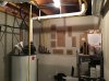
Here is what I am thinking. Any thoughts to improve? This is my first one and I have never punched down before or created by own Ethernet cables. I am thinking I can probably easily use 12 of my 16 port switch down here with at least (3) APs, (6) Cameras, and (3) network drops to rooms (office, bedroom, theater). I might also end up putting an 8 port POE switch upstairs just to make it many less cables to have to pull from basement all the way to attic.

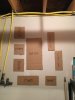
Most of the cables will be routing straight up from this layout into the joist space out to my garage, then through PVC conduit up to the attic.

Appreciate any help here.
 

Attachments

TonyR

IPCT Contributor
Joined
Jul 15, 2014
Messages
16,699
Reaction score
38,859
Location
Alabama
I agree with @drunkpenguin about the punchdowns. Buy pre-made patch cables and hide the excess as mentioned below. Save your crimping RJ-45 chore to when you have to minimize hole size when passing the connector-less cable through walls headed to/from the cameras, etc.

Your backboard would be an ideal application for Panduit's 'Panduct'. As a municipal traffic signal tech '73 to '04 I was stuck with designing and building the PLC-based controls for a city park's tennis & basketball court lighting and kid's playground water feature. I also did storm water lift pumps and muni bus automated washing systems wherein their control panels used this Panduct system as well. That was 15 years ago and I have no pictures but basically it was similar to the image below.

cp4.jpg

The Panduct allows you to group and neaten all wiring and separate power and data. It's available in a multitude of widths, depths and at least in gray and black. It cuts and installs easily, allows modifications and additions to the wiring easily and allows cable and conductor slack to be coiled, tied and hidden. Great stuff!

04-black-wide-slot-application.jpg
1031_279.jpg panduct1.png
 
Last edited:

greg_mitch

Pulling my weight
Joined
Mar 27, 2017
Messages
178
Reaction score
122
Good idea on the panduct. I already have a 1,000ft roll of CAT6 solid cable so buying premade cables is out. Also, I don't really know the distances so it is impractical to prepurchase terminated cables. I was planning to buy premade patches for between patch panel and the switch. I suppose the patch panel is a bit above and beyond, but beyond needing to punch down, I think fairly small amount of extra work.

I think the main benefit is that the solid cable goes to the punch down and the stranded cable can be routed between panels and switches. Either way, I was really looking for feedback on the layout.
 

mat200

IPCT Contributor
Joined
Jan 17, 2017
Messages
13,892
Reaction score
23,182
Good idea on the panduct. I already have a 1,000ft roll of CAT6 solid cable so buying premade cables is out. Also, I don't really know the distances so it is impractical to prepurchase terminated cables. I was planning to buy premade patches for between patch panel and the switch. I suppose the patch panel is a bit above and beyond, but beyond needing to punch down, I think fairly small amount of extra work.

I think the main benefit is that the solid cable goes to the punch down and the stranded cable can be routed between panels and switches. Either way, I was really looking for feedback on the layout.
Hi Greg,

Are those water lines next to your potential location? If so I would put your storage shelf on that wall, and your data cabinet / rack / wall board on the wall under the hvac.

Personally I prefer a patch panel, switch, nas, + nvr in a mini-cabinet / or rack of some sort with the supporting wood wall panel for the router, "modem", and other easy to wall mount units.
I also wall mounted the UPS with a nice 2x4 supporting blocks and short wood shelf.

When wiring I have found that wires take up more space than a box diagram initially assumes, so plan for extra space for wiring.
 

TonyR

IPCT Contributor
Joined
Jul 15, 2014
Messages
16,699
Reaction score
38,859
Location
Alabama
Yes, the second image (with all blue cables) shows vertical punch down RJ45 patch panels with black Panduct. I also use my Brother labeler machine a lot on the Panduct and back panel, with 1/2" white tape and black letters, as those little boxes for a Sharpie are too small to write in.
I've also numbered cables with wraparound Ideal or Brady numbers and put a legend card on the backboard showing where runs go ("Cable #4: MBR N. Wall" or the like).
 

TonyR

IPCT Contributor
Joined
Jul 15, 2014
Messages
16,699
Reaction score
38,859
Location
Alabama
Finally, if wiring or layout is extensive, I use The Draw module of OpenOffice to create a schematic-like layout (see screenshot below) of the backboard to help document, much like I did here a couple of years ago when I installed some wireless access points in a VERY large, two story church building. It can be saved also as a PDF file.
I've found that doing so helps me down the road to modify or troubleshoot or, in the case of the church, helps me restore operation after someone else monkeys with it BEFORE they decide to call me! :winktongue:

OpenOfficeDraw_1.jpg
 

greg_mitch

Pulling my weight
Joined
Mar 27, 2017
Messages
178
Reaction score
122
Hi Greg,

Are those water lines next to your potential location? If so I would put your storage shelf on that wall, and your data cabinet / rack / wall board on the wall under the hvac.

Personally I prefer a patch panel, switch, nas, + nvr in a mini-cabinet / or rack of some sort with the supporting wood wall panel for the router, "modem", and other easy to wall mount units.
I also wall mounted the UPS with a nice 2x4 supporting blocks and short wood shelf.

When wiring I have found that wires take up more space than a box diagram initially assumes, so plan for extra space for wiring.
Those are natural gas pipes out of the gas manifold. No risk of water damage. I can't put the storage shelf on that wall as the sump pump is on the floor right by the water heater. I like the wall mount flat approach to save as much space in the small utility closet.
 

greg_mitch

Pulling my weight
Joined
Mar 27, 2017
Messages
178
Reaction score
122
Finally, if wiring or layout is extensive, I use The Draw module of OpenOffice to create a schematic-like layout (see screenshot below) of the backboard to help document, much like I did here a couple of years ago when I installed some wireless access points in a VERY large, two story church building. It can be saved also as a PDF file.
I've found that doing so helps me down the road to modify or troubleshoot or, in the case of the church, helps me restore operation after someone else monkeys with it BEFORE they decide to call me! :winktongue:

View attachment 22569
Great idea! The Unifi controller gives you an topology diagram once it is all hooked up and configured. I may see if I can print that out, might save some time. :)
 

greg_mitch

Pulling my weight
Joined
Mar 27, 2017
Messages
178
Reaction score
122
Small update. I did decide to switch walls and the wall storage rack just fits between corner and sump pump with still enough access. I need to run a cable to the office before I can swap the modem/router downstairs. The rest of the cabling might require a few days off for me from work to get routed. I will probably put my server on the bottom shelf of the rack to the side. This really cleans up the furnace room too as a lot of stuff had been just sitting on the floor previously. Didn't even have to put a new power outlet in as this was covered by the rack previously! Working out well so far. I plan to have different color patch cables for each type of device (WIFI AP, Camera, etc.).IMG_4731.jpg IMG_4732.jpg
 
Top