was a reader, now a member

Joined
Sep 4, 2019
Messages
9
Reaction score
0
Location
Dutch
Hi all,

I have been reading parts of the forum for a while now.... Very interesting how the Hikvision brick has been resolved. Great job!

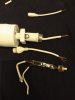
I was just wondering if anyone could help me find a pigtail cable for a 2032. Mine must have died.
:-(
 

Attachments

Joined
Sep 4, 2019
Messages
9
Reaction score
0
Location
Dutch
I have seen this topic. As far as i have been reading these mention a bad RJ45 connector and how to replace that by a box.
My RJ45 is just fine. The POE PCB is bad.
I have opened the pigtail and cut of bad wiring.
Maybe resoldering will fix it.
If it does not..... Any idea to get a new POE PCB?
 

Attachments

alastairstevenson

Staff member
Joined
Oct 28, 2014
Messages
15,930
Reaction score
6,779
Location
Scotland
Joined
Sep 4, 2019
Messages
9
Reaction score
0
Location
Dutch
I have 6 wires into the camera and 8 wires at the RJ45.

So I think i can not just cut out the PCB.
I think this PCB does the POE handshake.

If the PCB does only do the voltage magic from 12v input and the 48v POE handshake is being done inside the camera, i can just solder and shrinkwrap the old RJ45 back into the camera.
 
Joined
Sep 4, 2019
Messages
9
Reaction score
0
Location
Dutch
My doubt is....

Can i just cut out the PCB?

What is the PCB for?
Does this PCB make the POE handshake?

Does this do the 12v to 48v conversion
Or...
Does this do the 48v to 12v conversion?

I do not want to fry the camera.
 

alastairstevenson

Staff member
Joined
Oct 28, 2014
Messages
15,930
Reaction score
6,779
Location
Scotland
The PCB does the PoE interfacing with the switch, and the power conversion from 48v down to 12v which then supplies the camera. The camera only gets the Ethernet signals and the 12v power.
 
Joined
Sep 4, 2019
Messages
9
Reaction score
0
Location
Dutch
When i open the link i can see a cable without PCB.
My active POE inverter wont deliver voltage to the camera without a PCB. Because a handshake will not be made.

The cable I see is a cable with an external plug-in power option.
I rather power the camera by the active POE inverter.
 

alastairstevenson

Staff member
Joined
Oct 28, 2014
Messages
15,930
Reaction score
6,779
Location
Scotland
The PoE PCB is in the extra long cylindrical section at the RJ45 end.
Check out the product description.

I've used a couple of those to replace failed in-line PoE convertors.
 

alastairstevenson

Staff member
Joined
Oct 28, 2014
Messages
15,930
Reaction score
6,779
Location
Scotland
The in-cable PoE convertor also optionally allows the use of a 12v input if needed. That's what that barrel connector is for, just like your original broken one.
But you don't need to use that when the other end is in a PoE switch or active PoE injector.
 
Joined
Sep 4, 2019
Messages
9
Reaction score
0
Location
Dutch
I did open the link on my desktop PC instead of my smartphone, and now I can see the full picture.

THANK YOU!
You have found the holy grail.


I have found how to wire in the DS-2CD2032F-I camera onto standard UTP cable using T568B layout:

Hikvision - T568B
Orange ----- Orange / White
Yellow ------ Orange

Green ------ Green / White

Grey -------- Blue

Purple ------ Blue / White
Blue -------- Green
Brown ------ Brown / White
White ------- Brown

I have seen purple and brown wires are not in the wire going to the camera.

I have found orange and green wiring are the wires for positive and negative.

https://pinoutguide.com/visual/gen/poe.jpg
IEEE 802.3AT & AF = MODE A

----

Still just a little confused......
When I use an active POE injector, I can just cut the barrel out of the cable, solder matching colors of both ends together (add some heat shrink tubing) and add the injector straight onto the camera?

Like in the attachment?
 

Attachments

alastairstevenson

Staff member
Joined
Oct 28, 2014
Messages
15,930
Reaction score
6,779
Location
Scotland
I really don't understand why you'd want to cut the barrel off the connector.
All you needed to do is either :

Remove the original cable from inside the camera, taking the wires out of the JST connector and putting the new cable in its place, adding the wires to the connector and sealing the entry hole.
Or
Cut the old cable near the camera and join it to the new cable using heat-shrink sleeving as needed.
 
Joined
Sep 4, 2019
Messages
9
Reaction score
0
Location
Dutch
I think we don't understand each other well. English is not my native language. I will try to be clearer. I cut out the old barrel between the cable, because it no longer worked. Now I was wondering if I need to add a new circuit board if I use an active POE inverter. Or is it that I can just leave out the barrel and place the old RJ45 on the still existing wire near the camera? (like shown in the attached file i have uploadede before) That would be by far the easiest option. Replacing the entire wiring in the camera is not very easy. To do this properly, the entire camera must be dismantled. If the barrel is only needed to use an external power supply, then I can simply omit this, because I only use POE inverters. I do not use the external power supplies.
 
Top