A post showing my findings.
I have two IP cameras which draw ~3w of power but do not show any network activity at all. No blinking network activity lights on a switch, or the device showing up on a managed network switch.
Same symptoms powering with POE or 12v DC.
What's wrong?
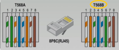
It appears the Ethernet cable was not the correct pin out. POE voltage was sent into the data lines.
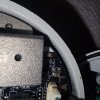
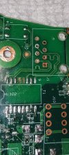
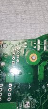
Connected directly to the TX & RX lines of the Ethernet jack input is an S16503G LAN transformer. An isolation transformer.
Checkout the burnt pin on this camera. That's pin 14 TX- .

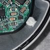
The LAN transformer has a bunch of little transformers inside. Something that could easily be burnt if too much voltage was applied, or maybe broken from impact in shipping. This photo shows one not potted in resin.


I bought these cameras used and have now received a refund since they were DOA.
The component costs $2 each off AliExpress. I'll buy some and report how it goes.
My message for Dahua Engineers: Please add circuit protection in case someone wires a network cable incorrectly and power is sent to the data lines.
I have two IP cameras which draw ~3w of power but do not show any network activity at all. No blinking network activity lights on a switch, or the device showing up on a managed network switch.
Same symptoms powering with POE or 12v DC.
What's wrong?
It appears the Ethernet cable was not the correct pin out. POE voltage was sent into the data lines.
Connected directly to the TX & RX lines of the Ethernet jack input is an S16503G LAN transformer. An isolation transformer.
Checkout the burnt pin on this camera. That's pin 14 TX- .
The LAN transformer has a bunch of little transformers inside. Something that could easily be burnt if too much voltage was applied, or maybe broken from impact in shipping. This photo shows one not potted in resin.
I bought these cameras used and have now received a refund since they were DOA.
The component costs $2 each off AliExpress. I'll buy some and report how it goes.
My message for Dahua Engineers: Please add circuit protection in case someone wires a network cable incorrectly and power is sent to the data lines.