IP Camera set-up without internet

bphillips

Young grasshopper
Joined
Oct 16, 2014
Messages
66
Reaction score
14
First thing you'd need to look at is the HP of your Winch and how it is wired, I presume thats a pretty heavy load so you'll need a pretty beefy relay.. actually a pair of them, one to turn motor on/off and another to reverse directions.. I wired something like this up for my Swamp Cooler to make my z-wave thermostat control it like a 2-stage air-conditioner, it had 2 speeds I had to switch through.. used three 24VAC Relays that could handle the 1HP motor and a bit of clever wiring... (FAN = Blower on Low, AC Stage 1 = Turn Water Pump on, AC Stage 2 = Blower on High)

Now for the timing and control you could probably write a very simple Arduino sketch to turn it on, wait XX seconds, then reverse.. does your winch shutoff or activate a clutch when it is fully open/closed or will you risk burning up the motor? You may need to add some switches to cut the relays when it maxes out.. One of the mPorts has a serial port on it, this might be able to plug right into the Arduino and trigger your sketch when the other sensors go off..

If you were to go this route you could forgo the mFi and just have the Arduino monitor the current, trigger the motors, and send an email via ethernet... If you have some programming experience there's alot more powerful stuff than an Arduino, but if your new to programming an ethernet Arduino is probably your best bet, its very easy to learn and alot of sample code/sketches are out there.
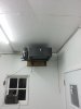
The winch wouldn't need to be too strong, maybe 1/5hp or so. We currently use a manual hand crank that can be easily cranked.

I looked into the Arduino stuff, it looks pretty over my head, but may be a fun thing to learn. As of now I am completely lost with how to use it, but I see the ability to. I assume if I went the Arduino route I wouldn't even need the mFI system, correct? Would I be able to rig up the Arduino system to automate the lowering and raising of the winch but also retain the ability to easily raise and lower the winch manually?

I wouldn't be too worried about burning up the winch motor. I could just time how long it takes to open the gates with the winch and use that same time for the open code and close code. In every situation, if the winch has to open the floor for X seconds it will then need to also close the floor for the same X seconds.
 

nayr

IPCT Contributor
Joined
Jul 16, 2014
Messages
9,329
Reaction score
5,325
Location
Denver, CO
Arduino is a very simple programmable microchip with a ton of General Purpose IO's you can use for all sorts of logic control. The hard part is going to be programing the logic, sounds like your already pretty mechanically/electronically fluent so I suspect you will have no problems with that part.. They tried there damnest with the Arduino to make the programing as simple and frustration free as possible, all the compilers and chip writers are all hidden in there sketch writing program so all you do is punch the code in. Getting the network stuff you want will probably require alot more code than operating the winch, but there are tons of sites with sample code you can harvest from for all that. (you basically just need to get on network, connect to a mail server.. probably w/out encryption or login, you might need to run a mail relay for it on your NVR)

if its a hand winch now you may just be able to hookup an electric motor rigged in to turn the hand winch, if its not a big motor you should be able to kill power to motor and operate it by hand.. might be a lil more resistance because your turning motor as well but thats fine.. for running off AC mains you'll want a motor thats reversible as its a lil more complicated than a DC motor where reversing the polarity to make it go the other way.. You'll remove or tap into the reverse switch with a small relay and then wire this up to the Arduino... You'll also need another relay on the motors power's power source/switch to turn the motor on and off.

Your sketch would then just go through a loop, checking current sensor status.. you'll do some logic to catch the current sensor changing state, when this happens you'll activate the main relay, then after some time the reverse relay will turn on, then wait for another fixed time to pass before shutting all relays. Then a last logic routine to connect to your mail relay and fire off a message to your phone's sms address saying job done and then start back from the beginning waiting for the current sensor to trigger it all over again.. Might also listen on a port you can connect to and manually trigger it, and disable it for testing and maintenance.

This would replace the mFi/mPort entirely, and by the time you get it working you'll have a bunch more ideas planned, like a failsafe to ensure the door is closed and not dumping grain all over the place... you could put a lil sensor in the chute or an ultrasonic sensor in the dryer to sense when it is full.. you'll be hooked and then trying to automate everything... Buy just an ethernet arduino first and a few cheap relay boards, a bread board and a pack of jumper wires.. you could simulate the current sensor with a simple switch and all the rest while you start learning the basics for cheap. Check out: http://www.freetronics.com/products/etherten you can add PoE to it and wire it up like your cameras.

When your all done wire it up in some nice dust/moisture free plastic cases and it'll keep on until you stop it.. You could do it cheaper with some more powerful microcontrollers, but you wont find them as easy to program or as much sample code and internet lessons to help you on your journey.

Also check out: https://learn.adafruit.com/category/learn-arduino for really good tutorials and ideas.

this is how much code it takes to turn something on/off on a timer.. instead of an LED it would be a relay.. and then you build up from there.


if you have a PC NVR there you might be able to get away without an ethernet Arduino if you can plug it into your NVR via USB and signal it to send the alerts.. you can get a knockoff non-ethernet arduino for nothing from china.. http://www.ebay.com/sch/i.html?_from=R40&_trksid=p2050601.m570.l1313.TR12.TRC2.A0.H0.Xarduino+uno&_nkw=arduino+uno&_sacat=0
 
Last edited by a moderator:
As an eBay Associate IPCamTalk earns from qualifying purchases.

bphillips

Young grasshopper
Joined
Oct 16, 2014
Messages
66
Reaction score
14
Thanks for the detailed help! I'll start digging into this in my free time and see what I can come up with. It's too late to get it going this year since we are already in the field. But that will give me another year to get it figured out.
 

bphillips

Young grasshopper
Joined
Oct 16, 2014
Messages
66
Reaction score
14
I have another question on how to handle LAN traffic once we get these point-to-point antennas put in. My cameras and NVR will be at the grain storage location. I'm going to install a router and switch at the site. Once I install the point-to-point antennas to beam the signal will I be able to keep this set-up and keep the on-site router to route the IP cam traffic to the NVR? In other words, I don't want the IP cam traffic going 2 miles down the antennas to the router at home and then getting redirected 2 miles back up the antennas to the NVR when the NVR is 100 feet away or less. So, can I create a separate LAN at the grain bins while still bringing a WAN signal from a different router? Does that make sense?
Untitled-1.jpg
 

nayr

IPCT Contributor
Joined
Jul 16, 2014
Messages
9,329
Reaction score
5,325
Location
Denver, CO
the Point to Point will be a transparent bridge, like hooking two switches together with an ethernet cable.. its up to the switches to discover which devices are on what port and they intelligently direct traffic.. not really routing, but you could put 2 different networks on subnets and force traffic through the routers.. could use a point to point VPN for extra security.

Switches only direct traffic to the port with that hardware associated with it, so anything talking locally wont traverse the wireless link.. all the devices on the other side of the bridge will appear to be on the port the bridge is plugged into.

Using routers will let you put firewall rules in place and filter traffic between the two sites, and/or use VPN; if you dont wish to do this then just hook them up to switches.
 

Lebeter

Getting the hang of it
Joined
May 6, 2014
Messages
103
Reaction score
18
repeating what nayr said, while you may get some broadcast traffic over the wireless shot, the rtsp streams will stay on the silo side with the nvr enabling you to only stream from the nvr webserver if you choose to only use switches. edge routers would enable more control over what packets and subnets could route/talk over the shot, and would allow encryption over the otherwise open wireless shot. would recommend something like an ipsec tunnel with blowfish for lower overhead otherwise your throughput may not be close to the theoretical throughput your wireless shot can achieve assuming you can configure it.

on the silo side of your diagram you might want to look at the ubnt edge router with multiple poe ports. combine two pieces of equipment into one. less headache, points of failure.
 

bphillips

Young grasshopper
Joined
Oct 16, 2014
Messages
66
Reaction score
14
Ok, so it sounds like it will be fine to have the router and switch at the grain bin site even after we beam internet up there from the house? Would I then plug the Ethernet cable from the antenna into the switch and not the router?

Some of this is a little over my head, but I think I understand it.
 

bphillips

Young grasshopper
Joined
Oct 16, 2014
Messages
66
Reaction score
14
I installed two of the cameras this weekend, we are still waiting on the electrician to run some conduit with Cat6 up the grain leg for the third camera and the antenna. We have a bunch of 3-phase running around the place so we want the Cat6 well protected.

I attempted to assign static IPs to the cameras and NVR using the configuration in the switch (ZyXEL GS1900-8HP) but couldn't figure it out. Am I going about that wrong? Do I configure it somewhere else?

Here are some pictures of the install.
 

Attachments

fenderman

Staff member
Joined
Mar 9, 2014
Messages
36,905
Reaction score
21,279
That is a managed switch..first thing about the switch is that you must assign a static ip address to it, the default is 192.168.1.1 and that will cause a huge issue if you connect it to a router that also has 192.168.1.1 as the default ip address...
login to the switch under configuration, set a static ip address outside your routers dhcp range...(or reserve that ip address in your router for your switch) hit apply, then on the top right, hit save...this is VERY important...if you dont hit save the switch will for get your changes upon power loss, this is dont so that you can revert back (by power cycling) if you are testing something...
As far as static ip's for the cameras...if you are using a vlan the switch will assign them, but if you are not, then use your router to assign static ip's...
 
Top