New RCA HSDB2A 3MP Doorbell IP Camera

David L

IPCT Contributor
Joined
Aug 2, 2019
Messages
8,019
Reaction score
21,001
Location
USA
Okay thanks: so to summarize/answer David's Qs:

1. Yes, I have a mechanical chime
2. The buzzing occurs even after I installed the power kit
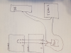
3. My 120V goes to the transformer in the basement. That one transformer splits two low voltage wire sets to by basement chime and my first floor chime

So , If I understood DavidL correctly:

Part I (today)
1. Replace current blown transformer with new 30VA, 24V transformer
2. Disable both chimes (for now) by separating F/T wires
3. Attach EZVIZ fuse wire to new transformer, and then turn circuit back on

Part II (When I get my resistors)
1.Keep basement Chime off (I only have one power damper kit)
2. Add 10OHM resistors between F/T of first floor chime
3. Add EZViz Power Kit as well to first floor chime
4. Connect chime wires of first floor back to F/T

I should now have EZViz working with my first floor chime, with the power kit, and the fuse wire both installed (power kit in chime, fuse wire at output of trans)

Did I get that right?
Where did you install the power kit? Which Chime? It needs to go in between the Smart Doorbell and the Chime.
Your continued buzzing/hum sounds like the power kit is not being able to regulate the load of your two Chimes, or the one Chime without the power kit if they are wired together, in my opinion.

Your system without Smart Doorbell; When the Doorbell button is pushed it completes the circuit from your Doorbell to your Chimes (Like a Light Switch), your existing transformer seemed to supply enough power to both Chimes. Your Chimes use no power until the circuit is closed.
When you add a Smart Doorbell it is like adding a second, or in your case, a third Chime to the system, which requires more load/watts. This, in my opinion, is what blew your transformer when you added the Smart Doorbell.

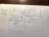
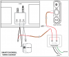
Can you show in a drawing, nothing fancy, how your two Chimes are wired and how your Doorbell is wired to them. As you can see in the diagram below, the Doorbell wire(s) go to the transformer as does the Chime and is wired together at the transformer.

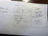
Here is a One Chime setup:
1586444838186.png

Thanks,
David
 

Attachments

Pliable Pixels

Getting the hang of it
Joined
Jan 7, 2020
Messages
44
Reaction score
82
Location
USA
@DavidL, @concord's diagram is exactly how mine is supposed to be wired. I tried to install the power kit inside the basement chime as well as the first floor chime aexactly as shown above in the diagram, both buzzed.

So right now I'm trying to take it one step at a time
a) Disconnect chimes, get new transformer working with the bell (which is where I'd like to know where exactly to put the DB1 fuse)
b) A few days later, when I connect chime, get the components right

Thanks
 

David L

IPCT Contributor
Joined
Aug 2, 2019
Messages
8,019
Reaction score
21,001
Location
USA
Thank You, This looks like a Ring diagram. I remember seeing one like this. My concern is how it shows the power kit installed, it may be just the drawing or how Ring's power kit works but our power kit needs to go in-between the Doorbell and the Chime not attached to it like this diagram. This is why our power kit comes with the Y cable. Think of the White from the Doorbell as (IN) and the Black from the Power Kit as (OUT) to the transformer with the Power Kit in-between. This allows the power kit to regulate the power going to the Chime.

1586446955697.png
 

David L

IPCT Contributor
Joined
Aug 2, 2019
Messages
8,019
Reaction score
21,001
Location
USA
@DavidL, @concord's diagram is exactly how mine is supposed to be wired. I tried to install the power kit inside the basement chime as well as the first floor chime aexactly as shown above in the diagram, both buzzed.

So right now I'm trying to take it one step at a time
a) Disconnect chimes, get new transformer working with the bell (which is where I'd like to know where exactly to put the DB1 fuse)
b) A few days later, when I connect chime, get the components right

Thanks
You are doing it right, my only suggestion is, if you can, wire up only one Chime at first, test it, if all is good, no buzzing/hum then try the second Chime. My thought on the two Chimes would be to wire them in series, in other words, one wire from Doorbell to transformer, the other wire from Doorbell wire to power kit then from power kit to the first Chime FRONT, like the Single Chime Diagram showed. From the FRONT on the CHime to the Front
@DavidL, @concord's diagram is exactly how mine is supposed to be wired. I tried to install the power kit inside the basement chime as well as the first floor chime aexactly as shown above in the diagram, both buzzed.

So right now I'm trying to take it one step at a time
a) Disconnect chimes, get new transformer working with the bell (which is where I'd like to know where exactly to put the DB1 fuse)
b) A few days later, when I connect chime, get the components right

Thanks
Do you have 3 sets of wires going to your transformer? One for each Chime and one for the Doorbell? I am working on a drawing to wire everything in series.
 

klunkerbus

Getting the hang of it
Joined
Sep 22, 2018
Messages
45
Reaction score
36
Location
Colorado, USA
... This allows the power kit to regulate the power going to the Chime...

View attachment 59088
Has anyone ever characterized what the "Power Kit" is? It is wired in parallel with the the mechanical chime. Its going to be limited on what it can do to "regulate" the power going to the chime. My guess is it is nothing but a power resistor inside a fancy package. Not really sure what else it COULD be.

Disclosure: I don't own one of these, but I follow the thread as a possible replacement for what I DO have...
 

David L

IPCT Contributor
Joined
Aug 2, 2019
Messages
8,019
Reaction score
21,001
Location
USA
Has anyone ever characterized what the "Power Kit" is? It is wired in parallel with the the mechanical chime. Its going to be limited on what it can do to "regulate" the power going to the chime. My guess is it is nothing but a power resistor inside a fancy package. Not really sure what else it COULD be.

Disclosure: I don't own one of these, but I follow the thread as a possible replacement for what I DO have...
Here is pictures of one open, I am trying to find the messages we already had on this very subject

1586449364266.png1586449395647.png

It's more than we first thought. Oh and unlike the Ring diagram, ours is wired in series.
 

Marty McFly

Getting the hang of it
Joined
Nov 23, 2018
Messages
53
Reaction score
37
Location
Canada
Has anyone ever characterized what the "Power Kit" is? It is wired in parallel with the the mechanical chime. Its going to be limited on what it can do to "regulate" the power going to the chime. My guess is it is nothing but a power resistor inside a fancy package. Not really sure what else it COULD be.

Disclosure: I don't own one of these, but I follow the thread as a possible replacement for what I DO have...
Great question. Would love to know more myself. Also, can we buy this power kit anywhere or does it need to come from the manufacturer?
 

David L

IPCT Contributor
Joined
Aug 2, 2019
Messages
8,019
Reaction score
21,001
Location
USA
Have you known them to go bad? I thought from the beginning that my issue could be a faulty power kit.
I seem to remember a few here reporting theirs was bad but can't totally confirm this. Also remember someone looking at it under an oscilloscope too. This thread is so big, bigger then my memory bank :) I will search oscilloscope in this thread and see if I can find the conversation of what does this power kit actually do. There was a real good conversation on this months back.

Found it, sorry Jack, almost forgot your message...


Pliable Pixels

Getting the hang of it
Joined
Jan 7, 2020
Messages
44
Reaction score
82
Location
USA
Hi @David L

1. It looks like I have 3 sets of wires coming out of my transformer. Please see first picture


2. Please see my "Part I" diagram. This is what I plan to do today. Can you comment if this is ok? (especially location of DB1 fuse)

3. Please see my "Part 2" diagram - this is when I plan to reconnect only one 1chime (because I only have one "power kit"). That shows the DB1 fuse, the power kit and the 10 ohm resistor. Not sure I need all of them.

I really don't want to blow yet another transformer later today.
 

Attachments

Last edited:

concord

Getting comfortable
Joined
Oct 24, 2017
Messages
665
Reaction score
741
Here is pictures of one open, I am trying to find the messages we already had on this very subject
It's more than we first thought. Oh and unlike the Ring diagram, ours is wired in series.
Thanks for opening it up. I have the first gen doorbell cam, no power kit was included. I just used a 10 Ohm power resistor across trans and front to eliminate the buzzing.

As for wiring, your diagram is the same electrically as the one I posted.
 

David L

IPCT Contributor
Joined
Aug 2, 2019
Messages
8,019
Reaction score
21,001
Location
USA
Thanks for opening it up. I have the first gen doorbell cam, no power kit was included. I just used a 10 Ohm power resistor across trans and front to eliminate the buzzing.

As for wiring, your diagram is the same electrically as the one I posted.
Actually I did not open the kit, one of our users here did, I just kept the pictures on file.

I was thinking more of connecting the second Chime in Series. Sorry for terrible drawing, real busy today. May could even put the power kit on second Chime in place of loop in drawing.

1586455966037.png
 

Attachments

Last edited:

David L

IPCT Contributor
Joined
Aug 2, 2019
Messages
8,019
Reaction score
21,001
Location
USA
Hi @David L

1. It looks like I have 3 sets of wires coming out of my transformer. Please see first picture


2. Please see my "Part I" diagram. This is what I plan to do today. Can you comment if this is ok? (especially location of DB1 fuse)

3. Please see my "Part 2" diagram - this is when I plan to reconnect only one 1chime (because I only have one "power kit"). That shows the DB1 fuse, the power kit and the 10 ohm resistor. Not sure I need all of them.

I really don't want to blow yet another transformer later today.
If you don't connect the Chimes you will be in no trouble in blowing your transformer unless your DB is bad...Just be sure and install the fuse/resistor. Very easy, from DB to fuse then to Trans. and back to DB.
 

Pliable Pixels

Getting the hang of it
Joined
Jan 7, 2020
Messages
44
Reaction score
82
Location
USA
If you don't connect the Chimes you will be in no trouble in blowing your transformer unless your DB is bad...Just be sure and install the fuse/resistor. Very easy, from DB to fuse then to Trans. and back to DB.
Thanks Part I completed without chimes. Fuse was installed at the transformer output (no space at DB end).
Hasn't blown yet.

Question on chime: I am going to connect one. Should I use both the resistor (just got it) AND the power damper kit?
 

David L

IPCT Contributor
Joined
Aug 2, 2019
Messages
8,019
Reaction score
21,001
Location
USA
Thanks Part I completed without chimes. Fuse was installed at the transformer output (no space at DB end).
Hasn't blown yet.

Question on chime: I am going to connect one. Should I use both the resistor (just got it) AND the power damper kit?
Only the power kit, fuse/resistor (that came with your DB) is if you don't have a Chime. If you are talking about the 10Ohm you purchased I cannot say, are you in the US? Most here, in the US, including me, do not need a resistor with our transformers.

EDIT: Sorry just saw a previous message from you stating you are in the US. So with No Chime setup use fuse that came with DB, when you add your Chime(s) later, use Power Kit.
 

Pliable Pixels

Getting the hang of it
Joined
Jan 7, 2020
Messages
44
Reaction score
82
Location
USA
Only the power kit, fuse/resistor (that came with your DB) is if you don't have a Chime. If you are talking about the 10Ohm you purchased I cannot say, are you in the US? Most here, in the US, including me, do not need a resistor with our transformers.

EDIT: Sorry just saw a previous message from you stating you are in the US. So with No Chime setup use fuse that came with DB, when you add your Chime(s) later, use Power Kit.
No problem.
Okay, so I now have:
a) A 24V 30VA transformer
b) EZViz DB1 fuse connected to the one of the wires that lead to the DB1 (connected to transformer side, not bell side, due to space)
c) One chime bypassed (wires connected together)
d) One chime active, with the EZViz power kit and no additional resistor

Chime works, Bell works.

Now lets see what happens in 24 hrs (when I first set it up, buzzing started the next day)

Thank you for your patient help.
 

David L

IPCT Contributor
Joined
Aug 2, 2019
Messages
8,019
Reaction score
21,001
Location
USA
No problem.
Okay, so I now have:
a) A 24V 30VA transformer
b) EZViz DB1 fuse connected to the one of the wires that lead to the DB1 (connected to transformer side, not bell side, due to space)
c) One chime bypassed (wires connected together)
d) One chime active, with the EZViz power kit and no additional resistor

Chime works, Bell works.

Now lets see what happens in 24 hrs (when I first set it up, buzzing started the next day)

Thank you for your patient help.
I think you are good, the fuse won't hurt anything, we found it is not a resistor like some manual suggest. Usually buzzing/hums come at night when the IR turns on, so check your Chime tonight. As far as your second chime, we may need to get more input from some of the experts here. I only suggest series wiring but don't have a second chime to test. I can say this, there has been a few here with 2 Doorbells, one Chime and one transformer that work. A little different wiring though since most Chimes are setup for a Rear Doorbell.
 
Top