Poor design of new high end Dahua bullet cameras - looking for a workaround

Slacker

Getting the hang of it
Joined
Feb 3, 2018
Messages
63
Reaction score
41
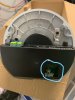
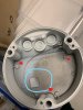
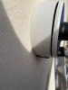
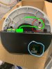
I recently got a new Dahua IPC-HFW7442H-Z4 camera and IVSS7008-2I NVR. I was very impressed with it until I went to mount the camera in it's permanent location. First when I had it mounted in a test location, I had to tighten the screw on the included camera housing so tight that I thought I was going to break something. They engineered the camera and housing to fit so well together that there is barely any rooms to make the connections. (Some CAD designer probably thought they are pretty clever) That wasn't a big problem for me since I only had a single CAT6 wire. When I went to mount the camera on the side of the building in its permanent location the surface was EIFS which I have mounted Dahua camera housings to before with no problem. The first problem was that I needed at least a 4-5" screw to catch the plywood behind the EIFS. Well apparently nobody makes a screw that length that is small enough to fit in the screw hole of the housing. (I checked, Home Depot, Lowes, Menards, Bomgaars, Fastenel). The longer construction screws are either a #9, #10 or bigger and will not fit. After I gave up looking for a screw that would fit, I decided to just drill holes through the back of the housing and not use the holes that were meant to mount the housing. Now I have the housing secured nicely to the side of the building. (Two stories up on a ladder in the freezing cold of Omaha, NE) I go to finish by mounting the camera to the housing and it won't go in all the way. It's 1/8" - 1/4" from the closing the housing. I took it back down and realized that they engineered the housing to fit the camera so tight that the back of the camera was hitting the head of the screw that I mounted the housing with. They actually even have a notched out spot for a spot that was too tight. I ended up just putting a ton of silicone around the housing and camera to fill the 1/4" gap and hoped for the best. It seems ok but man what an absolutely horrible design.

Does anyone have suggestions? This problem would apply to any of the cameras that have the same housing as IPC-HFW7442H, IPC-HFW7842H, IPC-HFW5842H.

Rant over
 

dudemaar

Known around here
Joined
Aug 18, 2018
Messages
1,191
Reaction score
2,540
Location
Canada
Stainless steel set screws need lube to prevent gulling. I have used 3-4 " desk screws before, sometimes you have to ream the hole out a little. Was the safety cable machine screw tightened all the way down?
 

Arjun

Known around here
Joined
Feb 26, 2017
Messages
9,118
Reaction score
11,160
Location
USA
Sometimes these designs are rushed and way too expensive to begin with. I'm not a huge fan of the mounting method on this model. Its not fail-proof and quite easy to damage something along the way.
 

mat200

IPCT Contributor
Joined
Jan 17, 2017
Messages
13,957
Reaction score
23,264
... The first problem was that I needed at least a 4-5" screw to catch the plywood behind the EIFS. Well apparently nobody makes a screw that length that is small enough to fit in the screw hole of the housing....
Hi @Slacker

FYI - this is one reason I like junction boxes... ( the PFA121 / 122 have the same base iirc, but different lids )
 

windguy

Getting comfortable
Joined
Sep 25, 2019
Messages
285
Reaction score
289
Location
Pacific Coast
@Slacker - I'm new to mounting cameras, so was curious about your camera mounting issues.
Are you using a junction box to mount your 7442 and which junction box are you using?
Based on the pics in the review of this camera, linked below, you need to use a junction box for this camera type. It can not be surface mounted without a junction box. True?

What mounting method did you use for the other Dahua cameras, which you said were no problem?
 

Slacker

Getting the hang of it
Joined
Feb 3, 2018
Messages
63
Reaction score
41
@Slacker - I'm new to mounting cameras, so was curious about your camera mounting issues.
Are you using a junction box to mount your 7442 and which junction box are you using?
Based on the pics in the review of this camera, linked below, you need to use a junction box for this camera type. It can not be surface mounted without a junction box. True?

What mounting method did you use for the other Dahua cameras, which you said were no problem?
If you look at the pics in the review, The junction box the 7442 camera is mounted to is what is included with the camera. I would really like to see if anyone could make all of the connections that are available on the camera inside the included junction box. Mounting directly to wood is easy because you can just use a short screw with a small head. The other cameras that I had mounted to EIFS used a PFA121 junction box and that worked great. A deeper junction box would solve the problem partially but I also think the holes you are supposed to use to mount the junction box to a surface should accommodate larger screw heads. You shouldn't have to search online for a specialty screw to mount a camera.
 

mat200

IPCT Contributor
Joined
Jan 17, 2017
Messages
13,957
Reaction score
23,264
A deeper base would solve the problem. With the 7442 model, the camera is integrated into the lid.
Thanks @Slacker

Looking closer at the reviews, I am imaging the problem. Do feel free to post any pictures which clearly show the limited space in the box. ( very frustrating I now imagine.. )
 

windguy

Getting comfortable
Joined
Sep 25, 2019
Messages
285
Reaction score
289
Location
Pacific Coast
@Slacker - understand better now, thanks.
Post #141 of the review thread I referenced shows detailed pics of the junction box.
Post #12, reviewer Wildcat does mention some caveats about the junction box.
I can see the issue with the mounting holes versus the PFA121 junction box that I have for a B5442. Having that deep channel does limit the maximum size screw head you can use. Not a very universal design for mounting. Your option of making new holes in the base seems reasonable and I'd use a decent size fender type washer to bulk it up provided you have room to do so.
Perhaps send a PM to Wildcat to get his take on your issue. Good luck!
 

Slacker

Getting the hang of it
Joined
Feb 3, 2018
Messages
63
Reaction score
41
@Slacker - understand better now, thanks.
Post #141 of the review thread I referenced shows detailed pics of the junction box.
Post #12, reviewer Wildcat does mention some caveats about the junction box.
I can see the issue with the mounting holes versus the PFA121 junction box that I have for a B5442. Having that deep channel does limit the maximum size screw head you can use. Not a very universal design for mounting. Your option of making new holes in the base seems reasonable and I'd use a decent size fender type washer to bulk it up provided you have room to do so.
Perhaps send a PM to Wildcat to get his take on your issue. Good luck!
This is the lag screw that I used. SPAX 1/4 in. x 5 in. Powerlag Hex Drive Washer Head Zinc Coated Lag Screw-4571010701277 - The Home Depot
I think the head is big enough that a fender washer isn't needed. I would like to do a test with play dough or putty of some type to figure out how much space is actually available in the junction box. The camera/lid fits so tight in the box that it still had 1/8" - 1/4" from closing the lid to the base because the the camera/lid is touching the screw head. I was concerned if I tightened the lid to much it would snap the plastic covering the electronics inside the camera/lid.
 

windguy

Getting comfortable
Joined
Sep 25, 2019
Messages
285
Reaction score
289
Location
Pacific Coast
@Slacker - nice choice on those lag screws. I would agree that a washer isn't required since the screws have a built in washer.
Plumbers putty might work for doing that fit check. Seems like a good idea to try.
I guess another mounting alternative is to add some type of mounting plate between the junction box and mounting surface. That's not as clean but it's an option if all else fails.
 

CCTVCam

Known around here
Joined
Sep 25, 2017
Messages
2,674
Reaction score
3,505
Maybe some feedback to Dahua if you haven't already. Workarounds are ok but without feedback the entire range could end up like this as it's refreshed.
 

Slacker

Getting the hang of it
Joined
Feb 3, 2018
Messages
63
Reaction score
41
Here are some pictures to help everyone understand the problem better. This is from a IPC-HFW5842H-ZHE that I still had in the box.
This first picture is that back side of the lid that the camera is attached to. Notice the cutout in the plastic I circled in blue. I can't imagine how anyone could utilize all the other connections with such small working space. Imagine being on top of a tall ladder fiddling with getting all the wires shoved in.
Camera Lid.jpg


This 2nd picture is the included camera housing. Notice the square raised section that I circled in blue. If you compare that to the first picture, you can notice that it matches up to the cutout I circled. The camera fits so tight in the housing that the raised square is actually inserted into the plastic cutout. Now look at the red dots. That is where I drilled new holes through the housing because you can not fit the head of a 4" or longer screw into the mounting holes in the housing. The same would apply to a concrete screw. Now I thought I had a clever workaround when I drilled the new holes into the housing except the housing fits so tight that the head of the screw prevents you from mounting the lid tightly to the base.
InkedCamera Housing Base.jpg


This is the camera IPC-HFW7442H-Z4 mounted to the side of a building which has EIFS for surface material. You can see the gap between the housing base and lid. The lid is on as tight as it will go because the inside of the lid is touching the head of the lag screws. If you aren't familiar with EIFS, it is a foam board on top of plywood or concrete that is then finished with a stucco type finish. You need a minimum 4" screw to get through the foam board and into the plywood.
Mounted Cam.jpg

Maybe @EMPIRETECANDY can report this to Dahua for a design fix before these cameras become more mainstream. As far as I know, there is not a deeper base option available for these cameras. I think @Wildcat_1 would agree this is a problem with these new cameras which have so much potential.
 

windguy

Getting comfortable
Joined
Sep 25, 2019
Messages
285
Reaction score
289
Location
Pacific Coast
@Slacker - thanks for sharing detailed pics. Very helpful.

I'd like to see a paper template made of the bottom of the camera housing, the black part shown in pic 1, and then lay that template into the junction box base so I can see where the camera base is positioned. The template should also include the cutout window which will enable you to line up the template in the correct position. The window cutout acts like a key. Seems like there should be enough room outside the template area to add your mounting holes and screw heads but I'm just eyeballing it. The template will confirm. I realize you've already poured over it for a long time but humor me. Thanks!

Also, is that a strain relief for the data cable circled in red below, path of cable in green or something like it?

Slacker's Camera Lid.jpg
 

Wildcat_1

Known around here
Joined
Dec 9, 2018
Messages
2,052
Reaction score
5,876
Location
US
Hey Slacker, been a while. I’m really surprised you have so much gap. On the 7442 (non Z4 I have in hand) it is tight, no gap at all. As I mentioned before certainly caveats with this style of built in junction box but have not seen any gap on this like you showed. BTW I use those power lags (SPAX) on every PTZ install, they are rock solid !


Here are some pictures to help everyone understand the problem better. This is from a IPC-HFW5842H-ZHE that I still had in the box.
This first picture is that back side of the lid that the camera is attached to. Notice the cutout in the plastic I circled in blue. I can't imagine how anyone could utilize all the other connections with such small working space. Imagine being on top of a tall ladder fiddling with getting all the wires shoved in.
View attachment 56023


This 2nd picture is the included camera housing. Notice the square raised section that I circled in blue. If you compare that to the first picture, you can notice that it matches up to the cutout I circled. The camera fits so tight in the housing that the raised square is actually inserted into the plastic cutout. Now look at the red dots. That is where I drilled new holes through the housing because you can not fit the head of a 4" or longer screw into the mounting holes in the housing. The same would apply to a concrete screw. Now I thought I had a clever workaround when I drilled the new holes into the housing except the housing fits so tight that the head of the screw prevents you from mounting the lid tightly to the base.
View attachment 56024


This is the camera IPC-HFW7442H-Z4 mounted to the side of a building which has EIFS for surface material. You can see the gap between the housing base and lid. The lid is on as tight as it will go because the inside of the lid is touching the head of the lag screws. If you aren't familiar with EIFS, it is a foam board on top of plywood or concrete that is then finished with a stucco type finish. You need a minimum 4" screw to get through the foam board and into the plywood.
View attachment 56022

Maybe @EMPIRETECANDY can report this to Dahua for a design fix before these cameras become more mainstream. As far as I know, there is not a deeper base option available for these cameras. I think @Wildcat_1 would agree this is a problem with these new cameras which have so much potential.
 

Arjun

Known around here
Joined
Feb 26, 2017
Messages
9,118
Reaction score
11,160
Location
USA
Were you required to predrill before using those SPAX power lags?

Hey Slacker, been a while. I’m really surprised you have so much gap. On the 7442 (non Z4 I have in hand) it is tight, no gap at all. As I mentioned before certainly caveats with this style of built in junction box but have not seen any gap on this like you showed. BTW I use those power lags (SPAX) on every PTZ install, they are rock solid !
 

Wildcat_1

Known around here
Joined
Dec 9, 2018
Messages
2,052
Reaction score
5,876
Location
US
You don’t have to. As I am usually up some height with PTZ’s then I’ll usually get a pilot hole started and go from there to make it a little easier but depends on your install location
and surface.

Were you required to predrill before using those SPAX power lags?
nd surface

Were you required to predrill before using those SPAX power lags?
 

Slacker

Getting the hang of it
Joined
Feb 3, 2018
Messages
63
Reaction score
41
@Slacker - thanks for sharing detailed pics. Very helpful.

I'd like to see a paper template made of the bottom of the camera housing, the black part shown in pic 1, and then lay that template into the junction box base so I can see where the camera base is positioned. The template should also include the cutout window which will enable you to line up the template in the correct position. The window cutout acts like a key. Seems like there should be enough room outside the template area to add your mounting holes and screw heads but I'm just eyeballing it. The template will confirm. I realize you've already poured over it for a long time but humor me. Thanks!

Also, is that a strain relief for the data cable circled in red below, path of cable in green or something like it?

View attachment 56038
What you circled in red is where you hang the wire that you can see in the housing picture. It's so you can hang the camera from there while you are talking on your phone. lol There is currently an Ocean between me and these cameras right now. I just had someone take a picture so I could clarify the problem rather than just my rant.
 
Top