R0 / DS-2CD2x32 BrickfixV2 brick recovery and full upgrade tool - enhanced.

alastairstevenson

Staff member
Joined
Oct 28, 2014
Messages
15,963
Reaction score
6,794
Location
Scotland
Well done, Doug.
Yes, SSH has been removed from the web GUI and if I remember correctly also from that firmware version.
But if it's still in that firmware you will be able to enable it with the Batch Configuration Tool.
Then get dumped in to psh and all its limitations.
 
Joined
Apr 13, 2019
Messages
15
Reaction score
1
Location
FRANCE
Hello,
I DID RECOVER MY MIN-SYSTEM! :)
As I've seen in the mtd8 images that there were a lot of spare space at the end of the partition and as the bad block in my cam was at the begining of the partition I first decided to relocate the useful data after the bad block and to boot manually to the good offset from uboot when needed.
Here are the steps I wanted to do:
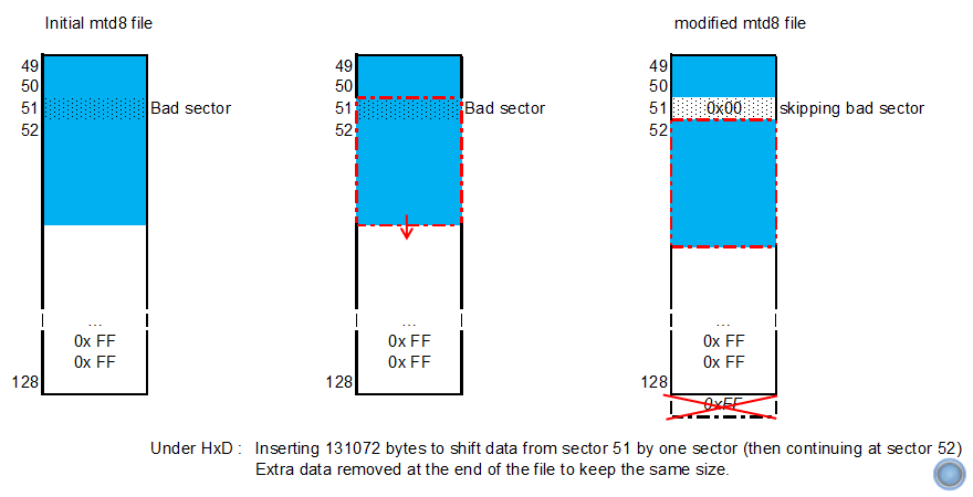
1) Creating the new file by inserting spare data (multiple of block size) at the begining of the file using HxD and deleting spare data at the end to keep the size of the file unchanged.
2) Find the mapping of the NAND from the u-boot point of view to be able to jump at the right offset (using "bootm" maybe)?
I didn't know how to get the NAND mapping in u-boot so I've played with "help" under u-boot and found the useful "show flash" command:
Code:
HKVS # show flash
RCT configured to NAND mode
main size: 2048
pages per block: 64
bst partition blocks: 0 - 1
ptb partition blocks: 1 - 9
bld partition blocks: 9 - 17
hal partition blocks: 17 - 25
ano_ptb partition blocks: 25 - 33
env partition blocks: 33 - 37
param partition blocks: 37 - 41
dpt partition blocks: 41 - 49
rcvy partition blocks: 49 - 129
krn_pri partition blocks: 129 - 193
krn_sec partition blocks: 193 - 257
rmd_pri partition blocks: 257 - 289
rmd_sec partition blocks: 289 - 321
app_pri partition blocks: 321 - 513
app_sec partition blocks: 513 - 705
cfg_pri partition blocks: 705 - 737
cfg_sec partition blocks: 737 - 769
dbg partition blocks: 769 - 897
With this command I found that the recovery partition was lying from blocks 49 to 128 which is confirmed by:
Code:
HKVS # show meta
bst      sblk: 0         nblk: 1         on: NAND
ptb      sblk: 1         nblk: 8         on: NAND
bld      sblk: 9         nblk: 8         on: NAND
hal      sblk: 17        nblk: 8         on: NAND
ano_ptb  sblk: 25        nblk: 8         on: NAND
env      sblk: 33        nblk: 4         on: NAND
param    sblk: 37        nblk: 4         on: NAND
dpt      sblk: 41        nblk: 8         on: NAND
rcvy     sblk: 49        nblk: 80        on: NAND
krn_pri  sblk: 129       nblk: 64        on: NAND
krn_sec  sblk: 193       nblk: 64        on: NAND
rmd_pri  sblk: 257       nblk: 32        on: NAND
rmd_sec  sblk: 289       nblk: 32        on: NAND
app_pri  sblk: 321       nblk: 192       on: NAND
app_sec  sblk: 513       nblk: 192       on: NAND
cfg_pri  sblk: 705       nblk: 32        on: NAND
cfg_sec  sblk: 737       nblk: 32        on: NAND
dbg      sblk: 769       nblk: 128       on: NAND
         sblk: 0         nblk: 0         on: DEFAULT
         sblk: 0         nblk: 0         on: DEFAULT
sm_stg[0]        sblk: 0         nblk: 0
sm_stg[1]        sblk: 0         nblk: 0
model name:
crc32:          0x9d57e812
But I still didn't know the base address of the NAND...
It doesn't matter because the "nandread" command allows to read data from a block and to write it into the DDR:
Code:
HKVS # help nandread
Help for 'nandread':
Usage: nand_read [ddr_addr] [block] [size]
read data from nand flash to ddr
need ddr address, start block in nand, data size
As I know that the "loadaddr" parameter shall point into the DDR I can read data from NAND to 0xc2000000 then use "dump" to show its contents
Code:
Usage: HKVS # help dump
Help for 'dump':
Usage: dump [8|16|32] [start address] - [end address]
Dump memory content in either 8-bit, 16-bit, or 32-bit mode
from specified starting and ending addresses
So let's verify that we can access the data from the recovery partition!
Code:
 HKVS # nandread 0xc2000000 49 2048
done!
HKVS # dump 32  0xc2000000
0xc2000000 d3 f0 21 e3
Yes! This is the data at offset 0 of the mtd8 partition (compared with the reference file under HxD). So let's find the data at the begining of the bad sector that is located at offset 0x40000 as I can see in HxD:
Code:
HKVS # nandread 0xc2000000 51 2048
done!
HKVS # dump 32  0xc2000000
0xc2000000 5d 07 48 bd
Hey! It doesn't match the data I can read at offset 0x40000 (2 sectors x 64 pages x 2048 bytes) in HxD!... But it matches the data located at offset 0x60000 (next good sector)!.....
Would it be possible that u-boot knows where are located the bad sectors and skips them? Yes! Which is confirmed by the following command:
Code:
HKVS # show bbt
Bad block found at 29
Bad block found at 51
Bad block found at 966
I beleive that I could have write the min-system from u-boot but as I didn't know how to do so I'd rather modified my mtd8 file under HxD by inserting 0x20000 dummy data at offset 0x40000 and deleting 0x20000 spare data at the end of the file to keep the same size.
Then I've launched the boot with the "init=/bin/sh" option as described in a previous post to be able to populate the mtd8 partition with the modified image:
Code:
# cat mtd8_skip_block51 > /dev/mtdblock8
Finally I still don't know the base address of the NAND flash from u-boot but my min-system is fully fonctional now! :)
I've tried the Hikvision TFTP update mode and it works!!!
 
Last edited:

alastairstevenson

Staff member
Joined
Oct 28, 2014
Messages
15,963
Reaction score
6,794
Location
Scotland
I DID RECOVER MY MIN-SYSTEM!
What can I say be be amazed at the level of persistence you're showing in exploring this stuff!

I beleive that I could have write the min-system from u-boot but as I didn't know how to do so
As your bootloader still has the nandread command, it should also have the nandwrite command also.
That is a powerful and useful command, and risky if the parameters given are incorrect or not understood.

Finally I still don't know the base address of the NAND flash from u-boot
The flash has to be addressed via a specific flash read or write command, with the base address being the offset of zero.

You've already figured out the flash layout from the bootloader commands you've used.
Here is an extract as shown by the kernel from a serial console log that also shows the flash layout :
Code:
[    1.058226] NAND device: Manufacturer ID: 0x98, Chip ID: 0xd1 (Toshiba NAND 128MiB 3,3V 8-bit)
[    1.067202] ambarella_nand_config_flash: 0x02e00140, 0x02c00140
[    1.073658] Bad block table found at page 65472, version 0x01
[    1.079877] Bad block table found at page 65408, version 0x01
[    1.091170] ambarella-nand ambarella-nand: ambarella_nand_probe: Partition infomation found!
[    1.099747] Creating 18 MTD partitions on "ambnand":
[    1.104811] 0x000000000000-0x000000020000 : "bst"
[    1.113353] 0x000000020000-0x000000120000 : "ptb"
[    1.121634] 0x000000120000-0x000000220000 : "bld"
[    1.130160] 0x000000220000-0x000000320000 : "hal"
[    1.138717] 0x000000320000-0x000000420000 : "ano_ptb"
[    1.147666] 0x000000420000-0x0000004a0000 : "env"
[    1.156343] 0x0000004a0000-0x000000520000 : "param"
[    1.165194] 0x000000520000-0x000000620000 : "dpt"
[    1.173925] 0x000000620000-0x000001020000 : "rcvy"
[    1.182838] 0x000001020000-0x000001820000 : "krn_pri"
[    1.191556] 0x000001820000-0x000002020000 : "krn_sec"
[    1.200579] 0x000002020000-0x000002420000 : "rmd_pri"
[    1.209605] 0x000002420000-0x000002820000 : "rmd_sec"
[    1.218704] 0x000002820000-0x000004020000 : "app_pri"
[    1.227847] 0x000004020000-0x000005820000 : "app_sec"
[    1.237087] 0x000005820000-0x000005c20000 : "cfg_pri"
[    1.246273] 0x000005c20000-0x000006020000 : "cfg_sec"
[    1.255555] 0x000006020000-0x000007020000 : "dbg"
[
I beleive that I could have write the min-system from u-boot but as I didn't know how to do so I'd rather modified my mtd8 file under HxD by inserting 0x20000 dummy data at offset 0x40000 and deleting 0x20000 spare data at the end of the file to keep the same size.
OK, so I get that you have re-written the active part of the mtdblock8 contents further up the flash memory, avoiding the bad block in the early part of the flash partition.
And that a nandread / bootm could be done using the new starting offset in the flash such that the end result in memory is the same.
I've tried the Hikvision TFTP update mode and it works!!!
But what I'm puzzling over is how the bootloader tftp update process would know to load up the min-system recovery environment, that does the actual updating, from the modified offset in the flash.
 
Joined
Apr 13, 2019
Messages
15
Reaction score
1
Location
FRANCE
Hello,

In fact relocating the whole file after the bad block was my first intention. I agree that proceeding this way wouldn't allow the TFTP update process to load up the min-sytem recovery environment. My thought was to launch it manually from u-boot.

But finally when I realized that u-boot was skipping bad sectors I didn't relocate the whole image but rather did the following rather:

So u-boot starts loading the image from sector 49 (at the beginning of the mtd8 partition) then skips bad sector 51 and continues loading the image from sector 52.

That's why it works!.
 
Last edited:

alastairstevenson

Staff member
Joined
Oct 28, 2014
Messages
15,963
Reaction score
6,794
Location
Scotland
I agree that proceding this way wouldn't allow the TFTP update process to load up the min-sytem recovery environment. My thought was to launch it manually from u-boot.
OK, that makes sense.

So u-boot starts loading the image from sector 49 (at the biginning of the mtd8 partition) then skips bad sector 51 and continues loading the image from sector 52.
Fascinating!
Thanks for the explanation.
It's not something I'd have thought of doing.
 

cillerucho

n3wb
Joined
Feb 27, 2019
Messages
12
Reaction score
0
Location
Spain
Hi, I was updating the camera but I have a problem,
- With the PC and the camera each on a wired connection (not WiFi) set the PC IP address to 192.0.0.128, subnet mask to 255.255.255.0
- the file digicap.dav is in the same folder as the TFTP
. The hikvision TFTP server puts initialized, but does nothing else
What could be the problem?
 

alastairstevenson

Staff member
Joined
Oct 28, 2014
Messages
15,963
Reaction score
6,794
Location
Scotland
What could be the problem?
Various possibilities spring to mind -

A firewall rule is blocking the camera UDP packets from reaching the tftp updater on the PC.
When first started, did a Windows firewall 'Allow inbound' confirmation dialogue box pop up? Was 'OK' clicked?
As a temporary measure, stop Windows firewall and see if that makes a difference.

An anti-virus / network protection program is blocking the camera UDP packets from reaching the tftp updater on the PC.
What AV is running, and can it be temporarily disabled?

The camera may no longer have the tftp updater facility in the installed bootloader.
Not likely on an R0 series camera, though it's quite a few years since Hikvision tried to discontinue the use of this program.

The seller may have modified the default IP address as used by the camera to probe for the tftp updater.
If you are able to manage it, a network capture on the PC as the camera is powered on while the tftp updater is running might yield some clues.

I hope that helps.
 

cillerucho

n3wb
Joined
Feb 27, 2019
Messages
12
Reaction score
0
Location
Spain
Various possibilities spring to mind -

A firewall rule is blocking the camera UDP packets from reaching the tftp updater on the PC.
When first started, did a Windows firewall 'Allow inbound' confirmation dialogue box pop up? Was 'OK' clicked?
As a temporary measure, stop Windows firewall and see if that makes a difference.

An anti-virus / network protection program is blocking the camera UDP packets from reaching the tftp updater on the PC.
What AV is running, and can it be temporarily disabled?

The camera may no longer have the tftp updater facility in the installed bootloader.
Not likely on an R0 series camera, though it's quite a few years since Hikvision tried to discontinue the use of this program.

The seller may have modified the default IP address as used by the camera to probe for the tftp updater.
If you are able to manage it, a network capture on the PC as the camera is powered on while the tftp updater is running might yield some clues.

I hope that helps.
I have disabled the AV windows and firewall windows and it still does not connect.
Attached some images to see if they can help
 

Attachments

alastairstevenson

Staff member
Joined
Oct 28, 2014
Messages
15,963
Reaction score
6,794
Location
Scotland
I have disabled the AV windows and firewall windows and it still does not connect.
Attached some images to see if they can help
The settings look OK, ignoring the gateway and DNS values as they should not be needed for this activity.
It has been noted that the tftp updater can be troublesome with Win10.
Sometimes just trying a few times works, power-cycling the camera.

Do you feel able to try a network capture with wireshark?
ie Start the tftp updater, start a network capture, power on the camera.
Leave for around 2 minutes then save the capture file.
If you attach it here it could be interpreted for you.
 

dknabe

Young grasshopper
Joined
May 17, 2015
Messages
39
Reaction score
6
Location
Dallas, TX
I have had tftp problems with directly connecting a camera to an Ethernet port on a computer. This was related to power up timing and Ethernet port activation by the OS. The problem is the Ethernet port is dead until there is a device on the other end. It takes the OS a while to recognize and activate the port after the camera is powered up. By then, the tftp request from the camera has already happened, so the tftp app is all crickets..

The solution is to connect a network switch or a router to the laptap and plug the camera into the network switch instead. The laptop Ethernet port then remains active even when the camera is power cycled. The tftp app then will see the tftp request from the camera when it happens. The camera only makes the tftp request once per powerup cycle.
 

cillerucho

n3wb
Joined
Feb 27, 2019
Messages
12
Reaction score
0
Location
Spain
I have had tftp problems with directly connecting a camera to an Ethernet port on a computer. This was related to power up timing and Ethernet port activation by the OS. The problem is the Ethernet port is dead until there is a device on the other end. It takes the OS a while to recognize and activate the port after the camera is powered up. By then, the tftp request from the camera has already happened, so the tftp app is all crickets..

The solution is to connect a network switch or a router to the laptap and plug the camera into the network switch instead. The laptop Ethernet port then remains active even when the camera is power cycled. The tftp app then will see the tftp request from the camera when it happens. The camera only makes the tftp request once per powerup cycle.
Thanks, works.
 

cillerucho

n3wb
Joined
Feb 27, 2019
Messages
12
Reaction score
0
Location
Spain
The settings look OK, ignoring the gateway and DNS values as they should not be needed for this activity.
It has been noted that the tftp updater can be troublesome with Win10.
Sometimes just trying a few times works, power-cycling the camera.

Do you feel able to try a network capture with wireshark?
ie Start the tftp updater, start a network capture, power on the camera.
Leave for around 2 minutes then save the capture file.
If you attach it here it could be interpreted for you.
I worked with the advice of dknabe.

Now i have another problem. Attached the image
 

Attachments

jericho

Getting comfortable
Joined
May 2, 2019
Messages
7
Reaction score
3
Location
Ireland
I spent a few hours trying to recover a bricked grey market DS-2CD2032-I this evening, so firstly a big thanks to all in this thread and especially the OP.

Couple of questions:
1. Followed all instructions and eventually got to the end successfully with no error messages. (took maybe 15 attempts)
That said, I still cannot access the web interface for the camera for some reason - I can't think of anything - unless perhaps that might indicate I got something wrong when using the hex editor?

Also, I have a HikWatch camera (not grey market) that I accidentally power cycled and it seems the brickfix firmware updated to that - so I've somehow bricked that as well. Is there an easier process for recovering non grey market cameras?

Would appreciate any help.
 
Top