YooSee SD-M5 doorbell: 1080p, PoE, RTSP, Onvif, only $66

The Konx (not Knox) website does not say anything about connecting a regular chime as far as I can see:


The specs on the Alibaba page are probably just wrong. The YooSee product page initially mentioned a PIR which is not there, they have now removed the reference to that. The Konxtech website I linked to above says it's a 1MP 720P camera while in reality it's a 2MP 1080p camera. These errors are probably just copy & paste errors when they write the page for a new product based on an older product's page.
 
All,

I have been looking for this type of camera I could use next to my keypad for my residential gate for quite some time.
I currently just have a GTO gate keypad, with no cameras or intercom system. I did wire up a relay so I can tell my android phone to open gate (Which has been nice)

I just got a Dell system from the outlet, and installed BI. I am still researching other cameras for the house and property, but I figured I would start with this one for my gate, so I know when someone is out there or if they cant get in.

I ordered the POE power supply, along with the doorbell camera from (e) bay. I will keep everyone posted once I receive and set it up. I will report back with pictures of my setup as well. I have read all 11 pages and Im excited to try this for myself. I have already run electric and 2 cat 5 cables to my gate that are waiting to be used.

Thanks to everyone for all of this valuable information!
 
The Konx (not Knox) website does not say anything about connecting a regular chime as far as I can see:


The specs on the Alibaba page are probably just wrong. The YooSee product page initially mentioned a PIR which is not there, they have now removed the reference to that. The Konxtech website I linked to above says it's a 1MP 720P camera while in reality it's a 2MP 1080p camera. These errors are probably just copy & paste errors when they write the page for a new product based on an older product's page.
opps... you are correct (dyslexia kicking in... Knox not Konx) Yep.. just checked the products link page on Konxtect website and the product details don't show the power regulator or make any mention of working with a mechanical doorbell)... bummer.

Will be interesting to see if Konx responds to my email on the question... although I'm not banking on it. I've built more TVs, radios an other electronic devices over the decades than I care to think about so my soldering skills are excellent. I'll have no problem cuttng the button traces or hacking the circuit board. On the downside other than a couple Fluke meters and soldering irons all my osilliscopes, test equipment etc are all long gone. Worse comes to worse I'll cut the traces to the button and wire in the leads from my mechanical doorbell. After all... my primary goal was only to let my NVR capture 24/7 video from the doorbell and piece is working fine. In the meantime I'm hoping one of you rocket scientist figure out a work around.
 
Last edited:
Hmmm... just discovered the calendar date/time displayed on the NVR recorded video coming from the SD-M5 doorbell does not match the date time of the NVR. I incorrectly "assumed" the time/date stamp on the video would be a function of the NVR as it does with my other cameras.

As it turns out... the doorbell has its own internal calendar/clock which "is" being recorded! (NVR places the date in the top right corner of the video, doorbell places it in the top left corner). Unfortunately the timestamp for the doorbell videos show the date as 1970-01-01. I don't mind if the doorbell utilizes its own internal time clock but since the SD-M5 doesn't come with a utility of any kind I'm stuck. Per the User Manual you can adjust the time and time zone via the Yousee app but I haven't installed it since most users on this forum seem to avoid it like the plague. (i.e., giving China access to your IP address, router, WiFi network and everything between :wow: ) So... I'm curious how are owners of this doorbell making adjustments, firmware updates etc., without installing the app... or is installing the app the only option?
UPDATE: What the heck... I figured no guts no glory. I went ahead and loaded the Yousee app on my phone. :eek: Launched it... gave it the permissions it wanted... and was able to get to the configuration file and settings. I was able to update the time and time zone, recording quality, alarms, sensitivity etc etc. It said there was a firmware update but I didn't install it. Anyway... I got the time displayed correctly and seemed good. BUT... as soon as I disconnected the camera from my router and plugged it back into my NVR... the date went back to showing 00:00:00 1970-01-01. grrr... So I reconnected the doorbell to my router... and this time held my breath as I did the Firmware update then made all the necessary time adjustments again. Exited out and reconnected it back to my NVR. No luck I'm back at midnight 00:00:00 in 1970. Whats odd is once its fired up... the time on the doorbell clock increments and continues to change as time goes by. after 24 hours the date changes to 1970-02-01. NOTE: Even the font used for the date and time display is different so the clock must be internal to the doorbell.
 
Last edited:
Bummer. Too bad it doesn't work the same way.

Oh, I should mention (forgot about this important detail). On the dahua and laview doorbells, the voltage drop only occurs when you change the configuration in their respective apps to "mechanical" chime.

Does the SD-M5 have a similar setting? Could be worth a shot.
 
Oh, I should mention (forgot about this important detail). On the dahua and laview doorbells, the voltage drop only occurs when you change the configuration in their respective apps to "mechanical" chime.

Does the SD-M5 have a similar setting? Could be worth a shot.
As mentioned earlier I installed the YooSee app on my phone. To check out your question... I went back into the configuration settings using the app but didn't see any hardware setting(s) in relation to chime setting (mechanical or otherwise) Since I was in the app again I also tried fixing the calendar /time again... still no luck. I would think for the doorbell to "retain" the date and time in the event of a power failure, it would have an internal battery or capacitor circuit acting like CMOS in a PC. The only way my doorbell shows the correct date and time is when the app is running on my phone and the doorbell is connected to the my network via wired or wireless. When I remove it from the network and connect it to my NVR its back to 00:00:00 1970. Unfortunately... the incorrect date and time coming from the doorbell is captured and saved on the video recorded by the NVR. :banghead:

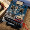
In case anyone is curious about the YooSee app... here are some screenshots of the various screens available to you via an Android device. Sorry for the poor photo quality but you'll get the idea. In the far left screenshot you will see a heading titled: Network Settings. I didn't include a screenshot of it but when selected it displays a screen showing your Device ID, Device Name, Firmware Version, Kernel Version, System Version, uBoot Version, LAN IP Address, MAC Address. In that same far left screenshot you will also see the title heading: Firmware Update : (followed by) It's already the latest! FYI: I updated the firmware using the app hoping it might fix my calendar/time problem (sigh). Anyway, after the update the latest version shows it to be 13.1.1.34 ( I have no idea what version was originally on my doorbell when I received it .. the app only said there was a later version... so I kicked the Update button.

settings.jpg
 
Last edited:
Here are some pics of the inside of the chime. According to some research I've done the four pins circled in red should be the output from the RF receiver. The one all the way to the right should be the one that sends the signal to the pcb when the receiver is triggered. But.... Either I'm doing something wrong trying to read a DC voltage on it or I got bad info cuz it stays at 0 volts. The other 3 pins stay a little above 4 volts.
But if I close the circuit by bridging the two outer pins (right and left pins) it triggers the chime. If all else fails I guess I could buy a wireless chime from Home Depot and make it wired by using the existing wire and run it from the pins on the button of the DoorBell pcb to the RF receiver. It would be the same concept as bridging the pins on this RF receiver to trigger the chime and voltage should match up.

I'd like to figure out though how to use a direct wire from the doorbell button to a always open relay that could close the circuit using the 2v DC of the doorbell on my 120v mechanical doorbell

chime.jpg20191021_174659.jpg20191021_175046.jpg
 
Last edited:
Here are some pics of the inside of the chime. According to some research I've done the four pins circled in red should be the output from the RF receiver. The one all the way to the right should be the one that sends the signal to the pcb when the receiver is triggered. But.... Either I'm doing something wrong trying to read a DC voltage on it or I got bad info cuz it stays at 0 volts. The other 3 pins stay a little above 4 volts.
But if I close the circuit by bridging the two outer pins (right and left pins) it triggers the chime. If all else fails I guess I could buy a wireless chime from Home Depot and make it wired by using the existing wire and run it from the pins on the button of the DoorBell pcb to the RF receiver. It would be the same concept as bridging the pins on this RF receiver to trigger the chime and voltage should match up.

I'd like to figure out though how to use a direct wire from the doorbell button to a always open relay that could close the circuit using the 2v DC of the doorbell on my 120v mechanical doorbell
Resized for my own edification so I could take it all in. Definitely sounds like your on the right path. Now I'm regretting not purchasing the chime. The seller tried to perswade me. It was only another 8 bucks. If I order now I'm looking at another months before I can move forward. Sheesh.
seeker.jpg
 
Any BlueIris users out there with this doorbell who can respond to these questions? NOTE: I don't use BlueIris... my SD-M5 is connected via POE to a Lorex NVR.

1) Does the date timestamp generated by the doorbell appear in your video captures? If so... have you be able to adjust and save the time/date? (Sure wish I could figure out how to change or disable the datestamp of the SD-M5)
2) My NVR shows "multiple" resolution settings being available. I've tried selecting multiple options... including (1080P) 1920x1080. No matter which I apply and save, it always defaults back to (HVGAW) 640x360. Have you been able change the resolution with BI?

These are the only settings I have access to. Not sure if any of them are the problem or its simply a compatibility issue with the Lorex not recognizing the SD-M5 (being able to push the setting changes)
toopost.jpg
 
Any BlueIris users out there with this doorbell who can respond to these questions? NOTE: I don't use BlueIris... my SD-M5 is connected via POE to a Lorex NVR.

1) Does the date timestamp generated by the doorbell appear in your video captures? If so... have you be able to adjust and save the time/date? (Sure wish I could figure out how to change or disable the datestamp of the SD-M5)
2) My NVR shows "multiple" resolution settings being available. I've tried selecting multiple options... including (1080P) 1920x1080. No matter which I apply and save, it always defaults back to (HVGAW) 640x360. Have you been able change the resolution with BI?

These are the only settings I have access to. Not sure if any of them are the problem or its simply a compatibility issue with the Lorex not recognizing the SD-M5 (being able to push the setting changes)
View attachment 49295
/onvif1 is path for 1080p. /onvif2 is path for 640.
 
So here's what I've come up with so far to try and get the Doorbell to work with a 120v mechanical door chime. I've found that the 4 pin button on the doorbell pcb is a always open circuit and I'm about 99% sure when closed it allows 2.2v DC to flow through the top 2 pins to the bottom 2 pins. The other 1% would be a error if by chance the common ground I've been using to test isn't good (need to research this part some to be 100% sure). I found a Step-up that will convert the 2.2v DC to 5v1/A DC, which would be able to trigger a 5v relay capable of a 120v load.

step-up - Amazon.com: Comidox 1.5V 1.8V 2.5V 3V 3.3V 3.7V 4.2V to 5V DC-DC Step Up Power Module Voltage Boost Converter Board 0.9-5V to 5V 5PCS: Electronics

relay - Amazon.com: Tolako 5v Relay Module for Arduino ARM PIC AVR MCU 5V Indicator Light LED 1 Channel Relay Module Works with Official Arduino Boards: Computers & Accessories
 
Last edited:
As an Amazon Associate IPCamTalk earns from qualifying purchases.
Speaking of Amazon... in looking for more information (i.e. hacks) on this doorbell... I found the KONX KW-05 version on Amazon France. (same model doorbell as the one I got off eBay ) You can read the reviews as well as questions and answers unfortunatley I didn't find any tidbits. I'm still trying to find a way to either set the time/date stamp or turn it off completely. Anyway... here's a link to the translated page. As you might expect some details get lost in translation. If you decide to check it out... give the redirect and translator a couple seconds to load.

On another note: Although no other owners of this doorbell have mentioned it... mine had a slight rattle to it if it was shaken. The lens focus on my camera was great so I had no need to break the warranty seal to adjust the focus (FYI: a great fix for out of focus doorbells discovered by @SecuritySeeker). Even though the focus was fine, I planned on breaking the seal anyway so I could investigate how "I" was might tackle hooking up my mechanical doorbell. FYI: Unlike @whoami, my thought process involves a less sophisticated approach, (i.e. cutting circuits rather than adding to them) Anyway, once I got the unit open I discovered what was causing the rattle. An antenna, (probably WiFi), was bouncing around inside the case. Fortunately with the help of jeweler loops and high power magnification I was able to determine where it belonged. The culprit was due to a poor solder joint (known to techies as a "cold solder joint"). They occur when the surface solder melts but doesn't flow over to the adjoining surface "or"... the after soldering, the joint is disturbed or moved before the solder has a chance to solidify which in turn fractures the bond. It's now been resoldered... all is good. NOTE: I wouldn't considering this as an area of concern. All electronics no matter how expensive have a margin of defects during the manufacturing process.

For the the most part its evident the circuit boards were assembled robotically and were not built with discrete components by child labor on a work bench. However, it is evident there was some work bench activity. I can't say if the work (i.e., modifications) were done as part of the original build or if earlier units might have been modified to fix something with the original design. The bench modifications are obvious as solder splashes and excess flux can be seen where components were added or changed. The IR emitters were either added or changed for some reason as well as the WiFi board that had the cold solder joint on the antenna.
cold solder joint.jpg

Flux Globs.jpg
Flux Globs2.jpg
 
Last edited:
As an eBay Associate IPCamTalk earns from qualifying purchases.
  • Like
Reactions: analogue
DAMN---fine call SecuritySeeker. Lens is threaded, but there is a set screw on side between the two mainboards it is a bit of a pain to get to. However image is already much easier on the eyes---almost in focus. [snip]
@Cinnman made reference to a set screw located on the doorbell camera lens. In the photo on the left provided by Cinnman... you can see there are two circuit boards that are sandwiched together more or less thus trapping the camera assembly. TIP: Once you get this board assembly out of doorbell housing, the two boards can be "separated" by simply pulling them apart. The only thing that holds them together is male/female plug assembly (see bottom photo). I figured since I had mine opened up I'd include a photo of the set screw in the event anyone want so tackle adjusting the focus. Pulling the boards apart will greatly ease the pain of trying to loosen and tighten the screw during the adjustment process. Obviously, it should go without saying anything you do once inside the unit should be done gently and with care.

lens adjustment.jpg
Board Connection.jpg
 
If the doorbell button is truly a physical button that gets depressed (spring loaded or buckling spring etc.) I figured I could totally isolate it from any and all circuitry. I just need the button so I can use it to close/short the existing wires of the current doorbell circuit. However... if its not actually a physical button but instead some sort of stationary capacitive touch sensor (PCT)... then hacking the USB chime would be the best solution. Do you have any idea what type of button it might be? [snip]
Answering my own question: Good news - Bad news. After tearing my unit apart I can confirm the actual button type used within this doorbell is a 6x6mm momentary tactile miniature push button SPST switch. NOTE: The button you touch when pressing the doorbell is a actually free floating isolated plastic disk that has a little protrusion on the back which in turn travels in and presses the miniature push button SPST switch. The good news is its a physical moving contact switch which would allow me to use it as I envisioned with some limitations. The bad news is this "little" switch is only rated at 12V. 50mA. My existing 1980's house doorbell uses a 16V transformer but... the current draw on the doorbell circuit is rated at 30VA! Even if I isolated the physical button used in this doorbell, hard wiring my existing mechanical doorbell circuit across this little switch would destroy it and depending on circuit tolerances within the SD-M5... I might even let the smoke out! :wow:

The other problem is everything about this doorbell circuit is sub-miniature. Locating and cutting the "correct" circuit traces as originally planned would be extremely difficult and/or simply unsoldering the button to isolate it is easier said than done (i.e. not for beginners) To keep from damaging the surrounding components/diodes due to heat, I would have to use my Weller digital soldering station and limit the iron wattage to no more than 20W (maybe even 15W) plus... even if using a pencil tip iron getting a solder sucker in there at the same time would be very tight (not to mention having to unsolder all four legs. Hopefully the attached pic will allow you to appreciate the sub miniature aspects of the problem.

Anyway... my "new" workaround, although not at exciting nor glamorous, will work. NET: I'm not altering any of the electrical circuits in the doorbell nor designing any lower voltage amperage auto switching circuitry etc. Since the SD-M5 as installed provided me with the primary function I was looking for (i.e., a live video feed 24/7)... I plan on simply removing the SD-M5 doorbell button/disk, fill in the void where it was removed and reassemble the SD-M5. Then... use the existing mechanical doorbell in my home as is. An already installed porch camera with motion detect will alert me "before" a person actually reaches the door. This will give me time to switch to my monitoring app and view the SD-M5 doorbell video before the the visitor even rings the bell. Pictures to follow once the project is completed.
Doorbell_Button_Internal.jpg
 
Last edited:
As an Amazon Associate IPCamTalk earns from qualifying purchases.
  • Like
Reactions: analogue
Does anyone know if the onboard IR can be disabled? The area I would use this already has IR coverage.

Thanks!
 
Does anyone know if the onboard IR can be disabled? The area I would use this already has IR coverage.
Thanks!
As you know the IR emitters allow the camera to see through the dark and capture clear images, that said... the "quickest - cheapest and fastest way would be to simply cover them with a ring of tape (as represented here by the ring of Red around the camera lens. The yellow dots represent the location of the IR emitters. Unfortunately I already uninstalled the app from my phone so I can't say if setting IR On/Off was a select-able option.
tape_ring.jpg
 
Last edited:
  • Like
Reactions: analogue
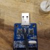
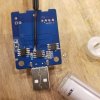
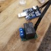
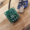
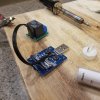
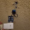
I have successfully hacked the SD-M5 into working with my mechanical chime.
I found a connection on the USB chime that received power when the chime was triggered. I originally thought it wasn't getting a consistent 4.98v (5v DC) but it turns out that the signal is so fast my multi-meter was unable to read it reliably. So long story short I did not need the 5v step up I ordered. I ended up buying a 5v relay and 5v step up from a company called Pololu. I came to the conclusion their products were more reliable than the average Amazon Chinese stuff. @Elton Norway is NOT joking when he said soldering these tiny joints is complicated. I had to use my cell phone camera and zoom in to make sure I didn't have any solder creating a short between joints. I know my soldering looks like $#!%.... But it works. I guess now Im going to either 3D print a box with standoffs, or make one to hold the components. Then I'm going to hard wire the USB receiver and relay on the other side of the wall from my doorbell in the electrical box in the wall that the 16v transformer for the chime is mounted to. Here's some pics to better explain how I accomplished this. Yes the pics are big, sorry, not going to resize them, I think I did enough work on this already and I should get a hall pass. FYI the doorbell wires go in the relay slots for common and NO (normally open). The NC is for normally closed.

Link to 5v relay: Pololu Basic SPDT Relay Carrier with 5VDC Relay (Assembled)

1st pic: Left wire = PWR (VDD) / Right = GND
2nd pic: Trigger wire = EN


20191101_192026.jpg20191101_192042.jpg20191101_192106.jpg20191101_192121.jpg20191101_191707.jpg20191101_191312.jpg
 
Last edited: