bls
Young grasshopper
The 4 digits are 6510. My existing system firmware version is V4.02.R12.00006510.10000, build date of 2014-03-29 12:36:22.
It was working fine as it was and I wouldn't have normally bothered to update the firmware, but discovered a problem when adding a photo-resistor to control the IR cut filter and figured it may be a firmware issue. Anyway, will get back to you and others with more about that once I have a chance to check it out using the new firmware.
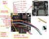
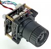
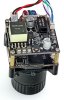
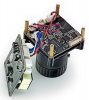
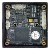
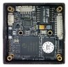
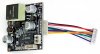
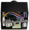
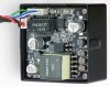
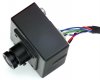
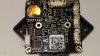
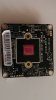
I bought a bunch of POE boards and have been making all my cameras, including these hi3518 board cameras, into POE powered ones. The board camera I just updated has audio so now off to add a mic.
This info might be useful if you didn't see it...
")
Where did you get your POE boards? I'm interested in doing the same thing. A link for the make/model would be great.
Not at all. And I would much rather see something than nothing at all. As for a photocell to control the IR cut filter, the control line goes to about 1V when pulled high using a 10K resistor to +5V, about 2.8V using 1K, about 3.5V using 470 ohms and to 4.2V using 180 ohms, but the current using <1K is over 3 ma. and an input line would normally pull-up much easier to nearly the voltage used (5v is actually 4.9V for the camera being used) so I'm guessing this is actually a 3.3V input. Also, the filter switches to night mode with > about .62V and back to day mode with < about .23V so anything from 1K to 10K should work OK, but something strange is happening. With the input high (>.62V) it takes 3 or 4 seconds for the filter to switch from day to night mode, which is typical, but then it switches back to day mode after about 10 sec's. It then switches to night mode again after another 3 or 4 sec's and keeps cycling like this repeatedly until the input is made low and it returns and stays in day mode. I was hoping this was a firmware problem that would go away when I updated to the latest version, but it didn't. Can someone with a camera having a cut-off filter confirm what I found to rule out that I perhaps have a defective camera? Or does this feature perhapes opperate different than any other camera I've seen?Thanks bls ...my "schematic" was shameful :bigsmile:
That is a bit strange, and the current to the switch cycles? A tricky one to isolate... It might actually be relief if it is a fault causing the refreshes. As far as I can understand the filter should simply settle at either one or the other state depending on the line voltage from the photocell. I can see why you were thinking firmware. The easiest method to check whats going on, and the only way I could do it, is by having another one side by side. Best would be any pre-assembled cam/filter module that uses at least the same cam module... that and my trusty multimeter :confused3:
Hi all,
did any of you ever get this cam running on an Android Device with IPCamViewer ? I can´t figure it out. Via Webinterface it runs perfectly and I can configure everything. Put in portforwarding in my router as well. I can get IPCamViewer to connect to the cam but only get a little Icon but no live feed.Got a couple of other different cams running on this software with no problems. Only this little beast is refusing.
I also downloaded the Android App for this cam "Family center" and get a picture there, too ! Gave it it´s own dyndns account - also no live feed.
Any suggestions ?
Thanks a lot in advance.
Oliver
I simply use BlueIris to view any of my cameras and saves having to fool around opening router ports and worrying about someone accessing and messing around with them.
Barry
Yes it is and I couldn't be happier with how well it works. I'm mainly a hardware person and often have problems figuring out how to get various programs (software) to do what they are supposed to, but have found BlueIris fairly easy to set up and do what I want it to. It's used mainly just on my local network to view and record a number of cameras set up around my house and garage, but while on holidays last fall I used it countless times to check on things back home from the other side of the country. Check out Blue Iris - Video Security Software
")